Frequently Asked Questions: Metric Threads - The Complete Reference
This FAQ section has been compiled from the most common questions received from engineers, designers, procurement specialists, machinists, and maintenance professionals. Questions are grouped by theme. If your question is not answered here, please contact our technical team.
Thread Basics and Identification
1. What is a metric thread and how does it differ from other thread systems?
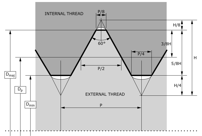
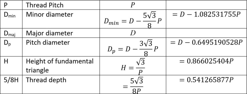
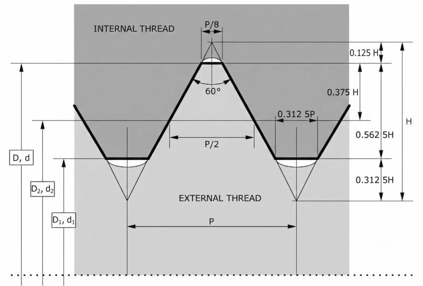
A metric thread is a screw thread whose dimensions - diameter and pitch - are expressed in millimetres, and whose basic profile is a 60° symmetrical V-shape as defined by ISO 68-1. The critical distinctions from other major thread systems are as follows. Compared to British Standard Whitworth (BSW) and British Standard Fine (BSF), metric threads use a 60° included angle rather than 55°, and metric diameters are expressed in millimetres while BSW/BSF use inches with threads per inch (TPI). Compared to the Unified Thread Standard (UNC/UNF), which is common in North America, metric and Unified threads share the same 60° angle, but the diameter-pitch combinations, designation systems, and dimensional details differ - they are not interchangeable. Compared to British Association (BA) threads used in instrumentation, metric threads are completely different in both profile and designation. In short: a metric bolt will not assemble into a BSW, BSF, UNC, or BA nut of the same approximate diameter. If in doubt, always measure or gauge before assembly.
2. How do I identify a metric thread from an unknown fastener?
The systematic approach is as follows. First, measure the major diameter (the largest diameter of the thread, measured across the peaks) using vernier callipers. If this is a whole number of millimetres (or very close to it - 6.0, 8.0, 10.0, 12.0 mm etc.), you almost certainly have a metric thread. If it is a fraction of an inch or corresponds to a fractional inch value (0.250", 0.375", 0.500" etc.), you likely have an imperial thread. Second, measure the pitch by counting the number of thread crests over a 10 mm length with a steel rule, or by using a thread pitch gauge - a set of leaf-type gauges, each marked with a pitch value, that you engage with the thread until you find a perfect fit. A metric thread will have a pitch expressed as a decimal number of millimetres (1.0, 1.25, 1.5, 1.75, 2.0 etc.). Third, if the thread is internal (in a nut or tapped hole), a set of plug gauges of known metric sizes will confirm the thread. Fourth, compare your measurements against the standard tables in this guide. Once you have major diameter and pitch, the thread is fully identified for standard metric threads. The designation will be M[diameter]×[pitch] - for example, M12×1.75.
3. What does the 'M' in M10, M12 etc. stand for?
The 'M' designates that the thread is to the ISO Metric standard (ISO 68-1 profile). It is followed by the nominal major diameter in millimetres. So M10 is a metric thread with a nominal major diameter of 10 mm, M24 has a nominal major diameter of 24 mm, and so on. The 'M' is not an abbreviation for "male" - metric designation applies equally to both internal (female) and external (male) threads.
4. What is the nominal diameter of a metric thread - is it the major, minor, or pitch diameter?
The nominal diameter of a metric thread (the number after M) refers to the major diameter - the largest diameter of the thread, measured at the crest (outermost peaks) of an external thread or the minor (innermost) dimension context of an internal thread. For a nut, the nominal diameter describes the bolt it is designed to accept, not the diameter of the nut itself. The nominal diameter of a metric fastener is therefore the same as the major diameter of the external (bolt) thread - and also the minimum major diameter of the internal (nut) thread. This is important: when someone says "an M16 nut," they mean a nut with an internal thread designed to accept an M16 bolt (16 mm major diameter external thread), not a nut that is 16 mm across its flats.
5. What is pitch and how is it measured?
Pitch is the distance in millimetres between adjacent thread crests, measured parallel to the thread axis. It is the most important secondary dimension of a metric thread after the diameter. For example, M10×1.5 has a pitch of 1.5 mm - the distance from one crest to the next is 1.5 mm. Pitch is the inverse of threads per unit length: a 1.5 mm pitch corresponds to approximately 16.9 threads per 25.4 mm (per inch). Pitch is measured directly with a thread pitch gauge or, less accurately, by counting crests over a known length with a steel rule. For metric threads, if no pitch is stated (e.g. simply M10 or M12), the coarse pitch for that diameter from ISO 261 is assumed. Coarse pitches are: M3 = 0.5, M4 = 0.7, M5 = 0.8, M6 = 1.0, M8 = 1.25, M10 = 1.5, M12 = 1.75, M16 = 2.0, M20 = 2.5, M24 = 3.0, M30 = 3.5, M36 = 4.0, M42 = 4.5, M48 = 5.0, M56 = 5.5 (all in mm).
6. What is the difference between major, minor, and pitch diameter?
These are the three fundamental diameters of a screw thread. The major diameter is the largest diameter - across the outermost crests of an external thread or the dimension a bolt is named after. The minor diameter (also called the core diameter or root diameter) is the smallest diameter - across the deepest roots. On an internal thread (nut), the minor diameter is the smallest diameter inside the threaded hole; this is the diameter closest to what a drill would produce before tapping. The pitch diameter (also called the effective diameter) is the theoretical middle diameter at which the thread width equals the space between threads. This is the diameter most critical for fit and function - thread gauges and tolerance specifications primarily address pitch diameter. For M10×1.5 the major diameter is 10.0 mm, the pitch diameter approximately 9.026 mm, and the minor diameter (internal) approximately 8.376 mm.
7. What is a left-hand thread and how do I identify one in the field?
A left-hand (LH) thread tightens when rotated anti-clockwise (when viewed from the end being tightened) - the opposite of the universal convention. To identify one: look at the thread helix direction. On a right-hand thread, the helix rises from left to right when the thread is viewed from the side (like a conventional screw). On a left-hand thread, the helix rises from right to left. If in doubt, try to engage the thread by rotating clockwise - if it refuses to engage but engages smoothly anti-clockwise, it is left-hand. Left-hand metric threads are designated by appending LH to the designation: M20×1.5 LH. They are used wherever rotation of the mating component during service would tend to unscrew a standard right-hand thread. Common applications include the left-hand side pedals of bicycles (to prevent unscrewing due to pedalling forces), certain gas cylinder valves (to prevent accidental interchange of flammable and oxidising gases), some vehicle wheel studs, and turnbuckle assemblies. Trojan Special Fasteners manufactures left-hand metric nuts across the full M3 to M56 range.
8. What is a multi-start thread and when would I encounter one?
A multi-start thread has two or more helical threads running in parallel around the cylinder. A standard thread has a single start (one helix). A two-start thread has two interleaved helices; a three-start thread has three. The advantage is that the lead (axial advancement per revolution) is a multiple of the pitch: for a two-start thread with 1.5 mm pitch, the lead is 3.0 mm - the assembly advances 3.0 mm for each complete revolution, double the rate of a single-start thread of the same pitch. Multi-start threads allow rapid assembly (faster engagement) while maintaining the thread angle and form advantages of a fine pitch. They are used in applications requiring fast actuation with good vibration resistance: pen caps, bottle closures, quick-release mechanisms, valve actuators, and some precision lead screws. The designation includes the lead (Ph) before the pitch (P): M10 Ph3P1.5 indicates a 10 mm diameter, 3 mm lead, 1.5 mm pitch (two-start). They are less common in standard fastener applications and are a bespoke item.
Thread Standards and Specifications
9. What are the key standards governing metric threads in the UK?
The primary standards are: ISO 68-1:1998 (basic profile - defines the 60° V-form geometry), ISO 261:1998 (general plan - lists all standard diameter-pitch combinations), ISO 724:1993 (basic dimensions - provides the derived dimensions D1, D2, d2, d3 etc. for each size), ISO 965-1:1998 (tolerance principles and data - the system of tolerance classes 6H, 6g etc.), ISO 965-2:1998 (limits of sizes for general purpose threads), and ISO 1502:1996 (gauges and gauging). In the UK, these are adopted directly as British Standards: BS 3643-1:2007 and BS 3643-2:2007. For aerospace applications, ISO 5855-1, -2, -3:1999 govern the MJ thread form. For fastener mechanical properties, BS EN ISO 898 (bolts and screws) and BS EN 20898-2 (nuts) apply. For electroplated threads, BS EN ISO 4042 applies, and for hot-dip galvanised threads, BS EN ISO 10684 and ISO 965-4/-5 apply.
10. What is the difference between ISO 261 and ISO 262?
ISO 261 is the comprehensive general plan - it lists all standard combinations of metric thread diameter and pitch, including coarse pitch series, fine pitch series, and constant pitch series. It covers a very large range of sizes and many pitch options for each diameter. ISO 262 is a selected subset of ISO 261 - it specifies the preferred sizes for screws, bolts, and nuts in common use. ISO 262 contains fewer size options and is the reference for the most commonly stocked and interchangeable sizes. When designing a new product, using sizes from ISO 262 maximises the probability of standard tooling and off-the-shelf fasteners being available. If a size from ISO 261 is chosen that is not in ISO 262, it may need to be specially manufactured - which is precisely the type of work Trojan Special Fasteners specialises in.
11. What does BS 3643 replace and what is its current status?
BS 3643 is the British Standard for ISO metric screw threads. It directly adopts and implements the ISO metric thread standards (primarily ISO 68-1, ISO 261, ISO 724, and ISO 965) for use in the UK. The current editions are BS 3643-1:2007 (Part 1: Principles and basic data) and BS 3643-2:2007 (Part 2: Specification for selected limits of size). These superseded the 1981 editions. BS 3643 is an active, current standard. Prior to metrication of British engineering (progressively from the 1960s), British industry used BSW, BSF, and BA threads, all of which are now effectively obsolete for new designs though still encountered in heritage and maintenance work.
12. Are DIN thread standards the same as ISO metric thread standards?
In practice, yes - for the common sizes. Germany's DIN 13 series (the original German metric thread standard) predated the ISO standards but was based on the same 60° metric thread geometry. When ISO harmonised metric threads, DIN adopted the ISO standards directly as DIN ISO documents. So DIN ISO 68-1, DIN ISO 261, DIN ISO 724, and DIN ISO 965 are identical in content to the corresponding ISO standards. In most cases, a DIN metric thread and an ISO metric thread of the same designation are identical. The exception is some older DIN-only specifications (like some parts of DIN 13 covering thread fits) that may have slightly different nomenclature or table arrangements, though the physical dimensions are essentially the same. For older German machinery, DIN 13 tables are the reference - but the thread dimensions match ISO.
13. What is the difference between tolerance class 6H and 5H for internal threads?
Both 6H and 5H denote internal metric thread tolerance classes per ISO 965-1. The number indicates the tolerance grade - the width of the tolerance band. Grade 5 is tighter than grade 6, meaning the allowable variation in pitch diameter is smaller for a 5H thread than a 6H thread. In both cases, the letter H indicates the tolerance position - the minimum pitch diameter starts at the basic (nominal) profile with zero deviation. A 6H thread is the standard for general-purpose metric fasteners: it provides a good balance between ease of manufacture, ease of assembly, and adequate strength for the vast majority of engineering applications. A 5H thread is used where closer control of the fit is needed - for example, in precision mechanisms, close-tolerance assemblies, or where consistent preload is critical. The tighter tolerance of 5H makes it harder and more expensive to manufacture, and assembly may be more demanding. For aerospace MJ threads, the standard internal tolerance is 4H5H (4H on pitch diameter, 5H on the minor diameter) - significantly tighter than general engineering 6H.
14. What tolerance class should I specify for a galvanised metric nut?
When metric threads are to be hot-dip galvanised, the zinc coating adds approximately 45–85 µm of thickness to each surface, which effectively increases the effective diameter of an external thread and decreases the clearance in an internal thread. ISO 965-4 and ISO 965-5 address this specifically. For a nut that will be tapped after galvanising to final size, specify 6H (standard), as the tapping removes excess zinc from the internal thread. For a nut that is galvanised after tapping (which is the more common scenario in practice), the internal thread must be tapped oversize before galvanising to accommodate the coating. The oversize tap position is specified as 6AZ (or equivalent local designation) - a special tolerance used specifically for pre-galvanising tapping. For electroplated (thin) coatings (typically 5–25 µm), 6G position (which provides a small positive allowance on internal thread diameter) is commonly used. Always specify the coating process and thickness when requesting thread tolerances for coated parts - the answer differs significantly between thin electroplate and hot-dip galvanising.
15. What is the 4g6g tolerance and where is it used?
4g6g is an external thread tolerance class used for high-strength and precision external threads. The first part, 4g, refers to the pitch diameter tolerance: grade 4 (tight tolerance), position g (small negative deviation from basic profile). The second part, 6g, refers to the major (crest) diameter tolerance: grade 6, position g. This combination is used for precision socket screws per ANSI B18.3.1M, certain aerospace fasteners, and high-strength bolts where precise fit and controlled preload are essential. It provides a tighter fit than the standard 6g external thread while maintaining adequate assembly clearance. The corresponding internal thread is typically 5H or 6H.
16. A customer specifies a "free fit" metric thread - what tap tolerance should be used?
A free fit corresponds to tolerance class 7H for the internal thread (nut or tapped hole), and 8g for the mating external thread (bolt or stud). Specify a 7H tap to produce a free-fit internal thread. This is the coarse-quality recommendation from ISO 965-1, providing the maximum clearance available within the standard metric thread system.
ISO 965-1 defines three quality levels for metric thread fits:
- Fine quality - 5H internally / 4h externally. Close-tolerance precision fit; minimal clearance. Used in precision mechanisms and aerospace.
- Medium quality - 6H internally / 6g externally. The universal standard for the vast majority of engineering applications.
- Coarse quality (free fit) - 7H internally / 8g externally. Deliberately loose; maximum clearance within the standard system.
A free fit (7H/8g) is the correct specification in the following situations:
- Long thread engagement - where cumulative pitch error over many turns would cause a standard 6H/6g fit to bind
- Assemblies exposed to contamination, surface oxidation, or minor in-service corrosion (agricultural, construction, outdoor equipment)
- Tapped holes receiving a thin coating after tapping - where a 6G position is insufficient but hot-dip galvanising is not involved
- Rapid production-line assembly where speed is critical and precision fit is not required
- Site-assembled structural connections where thread condition cannot be guaranteed
- Threads in materials subject to thermal distortion or dimensional variability (some castings, certain composites)
A free fit is not appropriate for precision mechanisms, vibration-critical joints, or any application where preload accuracy matters. In those cases, the standard medium-quality 6H / 6g fit should be specified. For the loosest tolerance class used specifically for hot-dip galvanised threads, see the separate question on galvanised thread tolerances.
Thread Selection: Coarse vs. Fine vs. Extra-Fine
17. In what situations should I choose fine pitch over coarse pitch?
Fine pitch should be specified over coarse pitch in the following circumstances. Vibration resistance: Fine pitch threads have a smaller helix angle, which means the thread wedge effect is more pronounced and the tendency to self-loosen under vibration is reduced. Critical automotive and aerospace connections (wheel nuts, cylinder head bolts, suspension components) almost universally use fine pitch. Thin-walled materials: When the parent material is thin (a thin-walled tube, a thin flange), a coarse pitch might not have enough thread turns engaged across the wall thickness. Fine pitch allows more thread engagement in the same axial depth. Adjusted tensile strength: For a given nominal diameter, a fine pitch thread has a slightly larger minor diameter and therefore a larger tensile stress area - the effective cross-sectional area resisting tensile load. Fine pitch bolts are therefore marginally stronger in pure tension than coarse pitch of the same nominal diameter. Precision adjustment: When a threaded component is used for fine adjustment (a micrometer, a focussing mechanism, a valve spindle), fine pitch provides more turns per unit of advancement, giving finer control. Hard materials: Fine pitch threads are sometimes preferred for tapping into very hard materials, as the smaller chip load per revolution is easier for the tap to handle.
18. In what situations should I always use coarse pitch?
Coarse pitch is the correct default for the following situations. General structural fastening: Most structural bolted joints, general machinery, and consumer products use coarse pitch because it is more tolerant of damage, contamination, and misalignment during assembly. Soft or low-strength parent materials: In aluminium, cast iron, plastics, or other soft materials, a coarse pitch thread has deeper engagement per turn, distributing load over a larger flank area and reducing the risk of stripping the female thread. Fine pitch threads in soft materials require greater engagement length to achieve equivalent strip strength. High-speed assembly: Coarse pitch threads engage and disengage faster, which matters on production lines using pneumatic or power tools. Fine pitch threads have more turns to engage and are more susceptible to cross-threading at high speed. Contaminated environments: Coarse threads are more tolerant of dirt, paint, rust, and minor surface damage. Fine pitch threads can be rendered unusable by relatively minor surface contamination. Availability and economics: Coarse pitch tooling (taps, dies, thread gauges) is universally available and economical. Fine pitch tooling is less common and more expensive, particularly for larger diameters.
19. What is an extra-fine or superfine pitch metric thread, and where is it used?
Extra-fine (sometimes called superfine) pitch threads have a pitch smaller than the standard fine pitch option for a given diameter. They are not listed in the main ISO 261 series for most sizes but fall within the constant pitch series (e.g. 0.75 mm, 1.0 mm, 1.25 mm applied to larger diameters than normal). Examples include M30×1.0 or M36×1.5, where the standard fine pitch for those diameters would be larger. Superfine pitches are used in aerospace applications (where they appear in the MJ thread series tables), precision instruments, optical equipment, hydraulic components, thin-walled tubing connections, and wherever maximum vibration resistance or the finest possible adjustment is needed. They require more thread engagement length to achieve adequate strip strength (because the thread depth is shallower), so they are inappropriate for short engagement applications or soft materials. Trojan Special Fasteners manufactures nuts in superfine and hard-to-find pitches across the M3 to M56 range - please enquire with your specific requirement.
20. Why does my M10 bolt not fit my M10×1.25 nut even though both are "M10"?
This is a very common issue. An M10 bolt without a pitch specification is assumed to be M10×1.5 (coarse pitch). An M10×1.25 nut is fine pitch. These two threads will not assemble correctly - the helix angles differ and the threads will either cross-thread or fail to engage properly. Always ensure that both the bolt and the nut (or tapped hole) have the same pitch. If in doubt, check the pitch of each component with a thread pitch gauge before assembly. This situation is particularly common when mixing components from different sources, when using fine-pitch nuts with standard bolts, or when working on automotive or precision machinery where fine pitch nuts are the norm. The rule is absolute: both components must be the same nominal diameter and the same pitch.
Thread Strength and Load Capacity
21. How strong is a metric thread? How do I calculate tensile strength?
The load-carrying capacity of a bolted joint depends on both the tensile strength of the fastener material and the tensile stress area of the thread. The tensile stress area (At) for a metric thread is calculated empirically per ISO 898-1 using the formula:
At = (π/4) × [(d2 + d3)/2]²
Where d2 is the basic pitch diameter and d3 is the minor diameter of the external thread (= d1 − H/6, approximately). This formula accounts for the fact that a screw under tension fractures through the threaded section - the effective area is neither the full cross-section nor just the minor diameter area, but an intermediate value. For common metric threads the tensile stress areas are approximately: M6 = 20.1 mm², M8 = 36.6 mm², M10 = 58.0 mm², M12 = 84.3 mm², M16 = 157 mm², M20 = 245 mm², M24 = 353 mm², M30 = 561 mm², M36 = 817 mm². The maximum tensile load is At × proof stress (or × UTS for ultimate load). For an M10×1.5 bolt in property class 8.8 (minimum UTS 800 MPa, proof load 640 MPa), the proof load is approximately 58.0 × 640 = 37,100 N (approximately 3.8 tonnes). Always use actual standard values from BS EN ISO 898-1 rather than approximations for design purposes.
22. What is thread stripping and how do I prevent it?
Thread stripping occurs when the threads in the nut (or tapped hole) - the internal thread - shear off under load before the bolt fractures in tension. This is a failure mode of the joint rather than the bolt. Stripping is more common when: (a) the nut material is weaker than the bolt material (aluminium nut with steel bolt is a classic combination), (b) the thread engagement length is too short, (c) the thread fit is too loose, or (d) the thread is damaged or contaminated. To prevent stripping: ensure adequate thread engagement length - a rule of thumb for steel-into-steel is at least 1× the nominal diameter (1D), increasing to 1.5D or 2D for aluminium or other soft materials. For a critical analysis, compare the shear area of the internal thread with twice the tensile stress area of the bolt - the shear area should be at least 2× the tensile stress area to ensure the bolt breaks before the thread strips. If this cannot be achieved in the available length of engagement (e.g. in a thin casting), use a thread insert (Helicoil-type) to increase strip resistance without modifying the external fastener.
23. What is tensile stress area and why is it different from the minor diameter area?
If you calculate the cross-sectional area of a bolt using just the minor diameter (the root diameter, the smallest diameter of the thread), you get a value that is too conservative - it underestimates the true load-carrying capacity. This is because the thread geometry means that in practice, fracture occurs at an intermediate diameter between the minor and pitch diameters - the stress is distributed across the helix of the thread root, not a clean circular cross-section. The tensile stress area is an empirically derived effective area that accounts for this - it gives results that closely match experimental bolt fracture loads. It is defined in ISO 898-1 (for bolts) and is the correct area to use in strength calculations. For an M10×1.5 bolt: minor diameter area ≈ π/4 × 8.376² ≈ 55.1 mm²; tensile stress area ≈ 58.0 mm². For an M10×1.25 fine pitch bolt: tensile stress area ≈ 61.2 mm². This illustrates why fine pitch bolts are marginally stronger in tension.
24. What thread engagement length do I need in aluminium, cast iron, and stainless steel?
Engagement length guidance varies by material combination. For steel bolt into steel nut/tapped hole: 1.0× nominal diameter is adequate for standard class bolts (8.8 or below); 1.25× is prudent for class 10.9 and 12.9. For steel bolt into aluminium tapped hole (a very common situation in automotive and aerospace): 1.5× to 2.0× nominal diameter is required because aluminium's thread shear strength is roughly one-third that of steel - the longer engagement compensates. For M10 into aluminium, aim for at least 15–20 mm engagement. Thread inserts (Helicoil-type, made from stainless steel wire) are strongly recommended in aluminium for any application involving repeated assembly/disassembly, as they protect the aluminium thread from wear. For steel bolt into cast iron: cast iron has variable thread shear strength but generally requires 1.25× to 1.5× engagement. For stainless-into-stainless: engagement length is less critical for strength (stainless has adequate shear strength) but galling is the dominant concern - see the separate question on galling. For metric nuts (as separate components rather than tapped holes): standard nut heights per BS EN ISO 4032 (style 1) and BS EN ISO 4033 (style 2, taller) are designed to provide thread strip strength equal to or greater than the bolt tensile strength, assuming matching property classes.
25. Is a fine pitch thread stronger than a coarse pitch thread of the same size?
In pure tension, yes - marginally. Because the fine pitch thread has a larger minor diameter (the root diameter is closer to the nominal diameter for fine pitch), the tensile stress area is slightly greater. For example, M10×1.5 (coarse) has a tensile stress area of approximately 58.0 mm², while M10×1.0 (fine) has approximately 64.5 mm² - about 11% more. However, this advantage is rarely the primary design driver. The practical strength of a bolted joint depends on many factors beyond just tensile stress area: the bearing area under the nut face, the friction coefficient, the preload achieved at a given torque, and - critically - the thread strip strength of the internal thread. Fine pitch threads, having shallower engagement depth per thread, can be more susceptible to internal thread stripping in soft materials even though the bolt itself is marginally stronger. The complete picture requires analysis of all failure modes for the specific joint, not just comparison of tensile stress areas.
Tightening, Torque, and Preload
26. What is bolt preload and why does it matter?
Preload (also called clamp load or bolt tension) is the tensile force induced in a bolt when it is tightened. This pre-tension is what actually clamps the joint together and makes it resistant to loosening, fatigue, and separation under service loads. A bolt that is not adequately preloaded will allow the joint to open and close under cyclic loads - this cyclic loading of the bolt itself (rather than the constant tension from preload) causes fatigue failure. Adequate preload is therefore essential for long-term reliability. The standard approach for critical joints is to tighten to a specified percentage of the bolt's proof load - typically 70–80% for non-permanent joints, or to yield (and sometimes beyond) for single-use torque-to-yield fasteners such as cylinder head bolts. Inadequate preload is one of the most common causes of fastener-related failures in service.
27. How do I calculate the correct tightening torque for a metric bolt?
The relationship between tightening torque T and resulting preload F is given by the simplified torque-tension formula, commonly expressed as:
T = K × F × d
Where T is the applied torque (Nm), F is the resulting bolt tension (N), d is the nominal bolt diameter (m), and K is the nut factor (also called the torque coefficient or friction coefficient factor). The nut factor K incorporates all friction effects in the joint (thread friction and under-head/nut-face friction) and typically ranges from about 0.10 for well-lubricated threads to 0.20–0.22 for dry zinc-plated threads. For unlubricated steel threads, K ≈ 0.20 is a common starting point. This formula is an approximation - the scatter in actual preload achieved for a given torque can be ±25% or more, depending on surface condition, lubrication, and assembly method. For critical joints, use calibrated torque wrenches, validate the K value for your specific conditions, or use alternative tightening methods (torque-angle, direct tension indication, stretch measurement). Published torque tables (such as those in VDI 2230 or fastener manufacturer data) give starting points for common combinations, but always verify against your specific joint conditions.
28. Why does lubricating a thread change the required torque?
Friction in a threaded joint acts in two places: in the thread flanks themselves and under the nut face (or bolt head face) as it rotates against the joint surface. Together these friction forces typically account for 40–50% (thread) and 40–50% (under-head) of the applied torque, with only about 10–15% of the applied torque actually going into creating bolt tension (preload). Lubricating the threads reduces the friction coefficient, which means a given torque produces more preload - and applying the same torque as for a dry thread to a lubricated thread can over-stress the bolt, potentially causing yield or fracture. When lubricant is specified (which it should be for stainless steel threads, and is good practice generally), the torque specification must be correspondingly reduced. A common lubricant like engine oil might reduce the required torque by 25–35% compared to dry assembly. Anti-seize compound (copper-based, nickel-based, or molybdenum disulphide based) reduces friction even further and should always be accompanied by a revised (lower) torque specification. Never use a "dry" torque specification with a lubricated thread.
29. What is torque-to-yield (TTY) tightening and when is it used?
Torque-to-yield (TTY) tightening deliberately tensions a bolt past its yield point - into the plastic (permanent deformation) zone. This approach maximises preload, minimises variation in clamp load between fasteners, and ensures all bolts in a pattern are at the same high preload. TTY fasteners are typically single-use - the plastic deformation means the bolt's properties have changed and it cannot reliably be reused. The classic application is cylinder head bolts in modern automotive engines, where TTY tightening ensures consistent head gasket clamping force. The process typically involves: (1) tightening to a specified initial torque (which takes up the stretch in the bolt to a safe elastic level), then (2) rotating a further specified angle (e.g. 90° or 180°) which carries the bolt into the plastic zone. The angle rather than torque controls the final elongation, making the process less sensitive to friction variations. TTY bolts are invariably fine pitch for the reasons described above (larger minor diameter = larger core area = greater elongation before fracture).
30. What methods are available for verifying bolt preload beyond a torque wrench?
Torque wrenches are the most common method but have significant inherent scatter (±15–25%). More accurate methods include: Torque-angle method - tightening to a snug torque, then rotating a specified additional angle; angle control is less sensitive to friction variation than pure torque control. Direct tension indication (DTI) washers - these deform under compression, and the gap between the DTI washer and the nut face is measured (with a feeler gauge) to confirm minimum tension; used extensively in structural steelwork per BS EN 14399-9. Bolt elongation measurement - measuring the increase in bolt length after tightening with a dial gauge or ultrasonic measurement; direct and accurate but requires access to both bolt ends. Ultrasonic bolt tension measurement - modern method using the change in speed of ultrasound through the bolt to infer tension; very accurate and non-destructive. Hydraulic bolt tensioners - apply tension directly to the bolt using hydraulic pressure, then the nut is tightened against the load; used for large-diameter bolts in pressure vessels, wind turbines, and flanged connections.
Thread Failure Modes and Prevention
31. What is thread galling and why does it particularly affect stainless steel?
Thread galling (also known as cold welding or seizing) is a form of adhesive wear where material transfers from one thread surface to the other during tightening, causing the threads to lock together irreversibly. It is the result of high contact pressure between thread flanks, combined with relative sliding motion, breaking down the thin oxide films that normally separate metal surfaces. Once the oxide films are disrupted, bare metal contacts bare metal and adhesion occurs - small asperities (microscopic high points) shear and transfer, building up progressively until the joint completely seizes. Stainless steel is particularly susceptible because: (1) it relies on a passive oxide film (primarily chromium oxide) for its corrosion resistance - this film is precisely what is destroyed by thread contact pressure during assembly; (2) austenitic stainless grades (A2/304, A4/316) are ductile and strain-hardening - under pressure, the metal smears and bonds rather than fracturing cleanly; (3) stainless has a relatively high coefficient of friction compared to carbon steel. The problem is further exacerbated by high assembly speed (heat generation), fine pitch threads (more thread engagement surface contact), and the use of the same alloy for both nut and bolt. Prevention measures include: using anti-seize lubricant (nickel-based, copper-based, or molybdenum-based); tightening slowly by hand before applying a torque wrench; using dissimilar grades (e.g. A2 bolt with A4 nut, or duplex stainless nut with austenitic bolt); specifying coarse pitch where possible; and choosing a slightly looser tolerance fit (7H/8g rather than 6H/6g) to reduce contact pressure.
32. What causes thread fatigue failure and how is it prevented?
Thread fatigue failure occurs when a cyclic tensile or bending load causes a crack to initiate at a stress concentration - almost always at the first engaged thread root, where stress is greatest - and propagate until the bolt fractures. It is the dominant failure mode for fasteners in dynamic (vibrating) applications. Fatigue is a progressive process: the bolt may survive millions of load cycles but then fracture suddenly without warning. Key factors that promote fatigue include: inadequate preload (a bolt with insufficient preload experiences the full range of applied load as cyclic stress; adequate preload keeps the bolt in constant tension, reducing its cyclic stress range); poor thread root form (sharp thread roots are stress concentrators; MJ threads specifically address this with a mandated large root radius); surface damage (scratches, nicks, corrosion pits, or handling damage at the thread root act as fatigue initiation sites); fretting (micro-movement at the thread root due to insufficient clamping). Prevention: specify adequate preload and use appropriate tightening methods; use MJ threads for aerospace and high-fatigue applications; specify rolled threads rather than cut threads for critical external fasteners (rolled threads have compressive residual stresses at the root, which retard fatigue crack initiation); avoid surface damage; ensure correct thread fit; and use thread locking methods for dynamic applications.
33. What causes thread stripping and how can I calculate whether my joint is adequate?
Thread stripping occurs when the shear stress in the engaged thread flanks exceeds the shear strength of the weaker material (usually the internal thread material in a nut or tapped hole). The shear area of the internal thread is:
Ass = 0.5 × π × D1 × Le
Where D1 is the minor diameter of the internal thread and Le is the engagement length. For the joint to be safe against stripping (with the bolt failing in tension before the internal thread strips), the shear area must be at least twice the tensile stress area of the bolt. This factor of two accounts for the difference between shear strength and tensile strength (shear strength ≈ 58% of tensile strength) and provides a safety margin. If the nut and bolt are the same material, the minimum engagement length is approximately:
Le (min) = 2 × At / (0.5 × π × D1)
Where At is the tensile stress area of the bolt. If the nut material is weaker (as in aluminium with a steel bolt), a correction factor J must be applied, increasing the required engagement length proportionally to the strength ratio. Most standard nuts per BS EN ISO 4032, 4033, and 4035 are designed to exceed this requirement - a standard nut of the correct property class will fail the bolt before the thread strips. The problem arises in tapped holes (not separate nuts), thin sections, non-standard materials, or when mixing property classes.
34. What causes vibration loosening of metric fasteners and how is it prevented?
Vibration loosening occurs when a fastener in service gradually unwinds under the influence of vibration or cyclic loading. It is not the same as thread stripping and does not require the applied load to be in the direction of unthreading. Vibration loosening is driven by transverse (sideways, perpendicular to the bolt axis) vibration that causes micro-sliding at the thread flanks - each micro-slip allows the bolt to rotate slightly, progressively reducing preload until the joint fails. The Junker test (DIN 65151) is the standard method for evaluating fastener resistance to vibration loosening. Prevention methods include: adequate preload (the primary and most reliable method - high preload resists transverse slip); fine pitch threads (smaller helix angle resists self-rotation); thread locking compounds (anaerobic adhesives such as Loctite 243 medium-strength blue fill the thread clearance and resist rotational loosening - effective for non-critical joints); prevailing torque nuts (all-metal or nylon insert types that impose a friction torque on the thread - effective but add assembly torque, which reduces achievable preload); locking washers (tab washers, spring washers, Nord-Lock wedge washers - effectiveness varies; simple split spring washers are widely criticised as ineffective under real vibration); castle/castellated nuts with split pins or wire (positive mechanical lock - reliable and widely used in aerospace and automotive); thread adhesive combined with adequate preload (belt and braces approach for critical applications).
35. What are the differences between prevailing torque nuts, thread-locking compounds, and mechanical locking?
Prevailing torque nuts (also called stiff nuts or self-locking nuts) resist rotation throughout assembly by imposing a friction torque on the mating bolt thread, regardless of bolt preload. Types include: nylon insert nuts (a deformable nylon ring grips the bolt thread; effective to about 120°C; relatively inexpensive; single-use in safety-critical applications); all-metal prevailing torque nuts (deformed thread or crimped body; suitable for high temperatures; used in aerospace and automotive). Thread-locking compounds (anaerobic adhesives) cure in the absence of air when confined between metal surfaces. Low-strength (e.g. Loctite 222, purple) can be removed with a standard spanner. Medium-strength (Loctite 243, blue) requires hand tools plus heat for removal. High-strength (Loctite 271, red) typically requires heat (>200°C) for removal. Thread-locking compounds do not add prevailing torque during assembly (unlike prevailing torque nuts) and therefore do not compromise preload achievement. Mechanical locking includes castellated nuts with cotter pins (or split pins), lock wires through drilled bolt heads, tab washers bent against a spanner flat, and various proprietary systems. These are positive locks - they physically prevent rotation rather than resisting it with friction. They are the most reliable solution for safety-critical, high-vibration, or hard-to-inspect applications. Mechanical locks generally allow the fastener to be fully preloaded before the lock is applied, which is the best practice for any fastener.
Thread Repair and Maintenance
36. How do I repair a stripped internal thread in aluminium or other soft material?
The standard approach for stripped internal threads is to use a thread insert. The most widely known type is the Helicoil (a brand name; the generic term is wire thread insert or coil thread insert). The process: (1) Drill out the damaged thread to the oversize STI (Screw Thread Insert) tap size - a specific drill size larger than the original. (2) Tap the oversize hole with a special STI tap (not a standard tap - the STI tap produces the thread that grips the outside of the insert, while the inside of the insert recreates the original thread size). (3) Install the wire insert using the installation tool provided; the insert winds in like a coil spring. (4) Break off the tang (the driving feature at the end of the insert) using the break-off tool. The result is a thread of the original nominal size inside the insert - the original bolt or fastener can be reused without modification. Wire inserts are made from stainless steel wire of rhombic cross-section; they are stronger than the original aluminium thread and are extremely wear-resistant. For high-temperature applications (beyond 250°C, where stainless grade 304/A2 inserts may be marginal), inserts in high-nickel alloy are available. Solid thread inserts (Keensert, E-Z Lok) are an alternative for damaged holes where the material has already been bored oversize, or where higher pull-out strength is needed. These are machined inserts press-fitted or screwed into an oversize hole. For very large stripped threads, the conventional repair is to plug-weld the hole (if material allows) and re-machine, or to bore oversize and fit a full insert bushing.
37. Can I use a standard tap to re-tap a damaged internal metric thread?
Yes, in most cases - provided the damage to the existing thread is not so severe that the major diameter of the tapped hole has been enlarged. A standard metric tap of the correct size and pitch will clean up a damaged or dirty thread by removing burrs and cross-threaded material, restoring the thread form to the correct profile. This is called thread chasing. Use the correct size and pitch tap, add cutting oil or tapping compound, and run the tap in slowly by hand - do not use power tooling for this operation. If the thread is not simply dirty or slightly damaged but has been stripped (the thread form is gone over one or more turns), re-tapping with the original-size tap will produce a thread that is oversize in pitch diameter - it will be loose and weak. In this case, step up to an oversize tap and fit an oversize bolt, or use the thread insert method described above. Thread chasers (a tool specifically designed for cleaning existing threads without removing material) are preferable to taps for cleaning operations on high-value components, as they carry a lower risk of removing material from the existing thread.
38. What is the difference between a cut thread and a rolled thread, and does it matter?
Cut threads are produced by removing material - using a tap (internal threads) or die (external threads), or by single-point turning on a lathe (both internal and external). The material is machined away to form the thread profile. Rolled threads (also called form threads or thread rolling) are produced by displacing material - cold-forming the thread profile into the surface of the workpiece without cutting. For internal threads, this requires a form tap (sometimes called a roll tap or fluteless tap). For external threads, thread rolling between hardened dies is the standard process for mass-produced bolts. The advantages of rolled threads over cut threads are significant: the work-hardening from the cold-forming process increases surface hardness at the thread root; the material flow creates compressive residual stresses at the thread root (fatigue cracks require tensile stress to propagate, so compressive residual stress at the initiation site substantially improves fatigue life - by 30–50% or more); the thread flanks have a smoother surface finish (no machined chip marks); the grain structure follows the thread profile rather than being cut through. For standard commercial nuts, the internal thread is almost always produced by cutting (tapping), because thread rolling for internal threads requires form taps and is only practical in specific materials and configurations. For critical external fasteners (aerospace bolts, high-strength studs), rolled threads are mandatory or strongly preferred. For the bar-turned fasteners produced by Trojan Special Fasteners, threads are produced by cutting using precision single-point turning tools.
Thread Coatings and Corrosion
39. What surface treatments are available for metric threaded parts and how do they affect thread fit?
The most common surface treatments for metric fasteners and their effects on threads are as follows. Zinc electroplating (bright zinc): coating thickness typically 5–25 µm; reduces thread clearance; tolerance position g or f (external) or G (internal) is specified before coating to allow for thickness. Hot-dip galvanising: coating thickness typically 45–85 µm per surface - significantly thicker than electroplate; internal threads tapped to position 6AZ (oversize) before galvanising, or tapped after galvanising to standard 6H; governed by ISO 965-4 and ISO 965-5. Zinc flake coating (e.g. Geomet, Deltacoat): thin coating (8–15 µm typically) with excellent corrosion resistance; generally used on external threads; tolerance position similar to zinc electroplate. Phosphate treatment (black or grey finish): very thin (1–10 µm), minimal effect on thread fit; adds some corrosion resistance and reduces galling tendency; often used with oil. Electroless nickel plating: uniform thickness coating regardless of geometry (unlike electroplating); 15–25 µm typical; provides excellent corrosion and wear resistance. Cadmium plating: now largely prohibited under RoHS regulations in Europe due to environmental toxicity; historically used extensively in aerospace for its low friction coefficient and excellent corrosion resistance in salt environments. Geomet/Dacromet (zinc flake): thin, controlled-thickness coatings applied by dipping and baking; commonly used for structural fasteners. The critical rule is: always specify the coating type and thickness when ordering threaded parts, and ensure the thread tolerances before coating are chosen to give the correct fit after coating.
40. What is hydrogen embrittlement and why does it affect high-strength metric fasteners?
Hydrogen embrittlement (HE) is a form of embrittlement caused by atomic hydrogen diffusing into a metal's crystal structure under stress, reducing ductility and causing sudden brittle fracture at stresses below the material's normal yield point. It is particularly dangerous in high-strength steels (property class 10.9 and especially 12.9, with tensile strengths above 1000 MPa) and in certain stainless steels. The hydrogen typically enters the steel during acid pickling (used to clean the surface before electroplating) or during electroplating itself (hydrogen is evolved at the cathode during plating). The risk increases with steel strength - low-strength steels (grade 4.8, 6.8) are relatively unaffected; grade 12.9 bolts are extremely susceptible. Prevention measures include: using alternative cleaning processes that do not introduce hydrogen (mechanical cleaning rather than acid pickling); using alkaline electrolytes rather than acid electrolytes for plating; performing a post-plating bake - heating the plated parts to 180–210°C for 8–24 hours within 4 hours of plating, which allows the diffused hydrogen to escape before the plating seals it in. BS EN ISO 4042 specifies hydrogen embrittlement requirements for electroplated fasteners, including baking requirements based on property class. The standard prohibits electroplating of grade 12.9 external threaded fasteners by conventional acid electroplating processes for this reason - alternative processes or zinc flake coatings should be specified instead.
41. How corrosion-resistant are standard metric fasteners, and what should I specify for harsh environments?
Standard carbon steel metric fasteners (property class 8.8, 10.9, 12.9) with no surface treatment have essentially no useful corrosion resistance - they will begin to rust within hours in wet conditions. The following options exist for progressively more corrosive environments. Zinc electroplate (5–12 µm): provides adequate protection for indoor or sheltered outdoor use in non-aggressive environments; life measured in hundreds of hours in salt spray testing. Hot-dip galvanising (45–85 µm): much better corrosion protection; suitable for exposed outdoor structural applications; salt spray life of thousands of hours. Zinc flake coatings: excellent performance-to-thickness ratio; widely used on structural bolts, automotive, and wind turbine fasteners. Stainless steel grade A2 (304): suitable for general outdoor and mildly corrosive environments; not suitable for marine or chloride-rich environments. Stainless steel grade A4 (316): the standard choice for marine environments, chemical plant, and coastal locations; contains molybdenum which substantially improves chloride resistance. Duplex stainless steel: greater strength and corrosion resistance than standard austenitic; used in offshore, chemical, and high-stress marine applications. For seawater immersion or subsea applications, super-duplex stainless, titanium, or specialist alloys are appropriate. For high-temperature applications, consider Alloy 625, Alloy 718, or specialist heat-resistant steels. Trojan Special Fasteners manufactures in standard stainless grades and carbon steel; for exotic materials, specialist suppliers should be consulted.
Aerospace and Specialist Threads
42. What is the MJ thread and why is it mandated for aerospace?
The MJ thread (Metric, J-form, controlled root radius) is defined in ISO 5855-1, -2, 3:1999. It uses the same 60° profile and the same pitch table as standard ISO metric threads but differs fundamentally in the external thread root: the root radius on an MJ external thread is mandated at between 0.15011P and 0.18042P a significantly larger and more precisely controlled radius than the optional, often negligible root radius on standard M threads. This controlled root radius dramatically reduces stress concentration at the thread root, which is the primary initiation site for fatigue cracks under cyclic loading. The result is a fatigue life improvement of 30–50% or more compared to equivalent standard M threads. MJ threads are mandatory for flight-critical fasteners in commercial and military aerospace by all major airframe manufacturers and by the relevant standards (Airbus ABD0031, Boeing BAC5974, MILSPEC references, and EN aerospace series). The standard internal tolerance for MJ threads is 4H5H (much tighter than the general-purpose 6H), and the standard external tolerance is 4h6h or 4g6g. MJ threads require dedicated gauging (MJ plug and ring gauges, not standard M gauges). An MJ bolt will generally fit a standard M nut of the same diameter and pitch (the bolt's larger root does not affect external thread engagement), but an M bolt should not be assumed to meet MJ requirements even if it fits - the uncontrolled root radius means fatigue life will be inferior.
43. Are MJ threads and M threads interchangeable?
They are dimensionally compatible in most cases - an MJ external thread can engage an M internal thread of the same nominal diameter and pitch, and vice versa. However, they are not functionally interchangeable in aerospace or safety-critical applications because: (1) an M bolt installed where an MJ bolt is specified will have a smaller or absent root radius and therefore inferior fatigue life - this represents a non-conformance and a potential safety issue; (2) tolerance classes differ - an MJ thread to 4h6h tolerance is considerably tighter than a standard M thread to 6g, and substituting a standard bolt may give inadequate fit or excessive clearance; (3) gauging differs - an M thread that passes M-series gauges is not guaranteed to pass MJ-series gauges. In summary: always follow the drawing specification. If an MJ thread is specified, supply an MJ thread. If an M thread is specified, the designer has accepted that standard M is adequate for that application.
44. What are the differences between tolerance class 4H5H and 6H for internal MJ and M threads?
Both classes apply to internal (female) metric threads - 4H5H for aerospace MJ applications and 6H for standard general engineering. The number denotes the tolerance grade (width of tolerance band): 4 is considerably tighter than 6. The first number in 4H5H (4H) applies to the pitch diameter; the second (5H) applies to the minor diameter. In 4H5H: the pitch diameter tolerance is approximately 60–70% of the width of a 6H tolerance - the thread must be machined to much closer limits. This demands more precise tooling, more frequent gauging, slower machining speeds, and more careful process control, all of which increase cost. The H position in both cases means the lower limit of the pitch diameter starts at the basic profile - no deliberate allowance. The tighter tolerance of MJ threads ensures maximum thread flank contact, minimising the micro-movements under load that can initiate fretting wear and fatigue. For general engineering, the additional cost of 4H tolerance is not justified; for flight-critical fasteners, the safety margin it provides is mandatory.
Manufacturing and Process
45. What is the difference between single-point thread turning, tapping, and thread milling for internal threads?
Tapping is the most common method for internal threads: a tap - a fluted cutting tool with the thread profile ground into it - is driven into a pre-drilled hole to form the thread. Tapping is fast and economical for small-to-medium sizes in materials of moderate hardness. Its limitations include: breakage risk in hard materials; inability to machine blind holes very close to the bottom; and difficulty with very large sizes (large taps are extremely expensive and difficult to handle). Single-point thread turning (on a CNC lathe) uses a single cutting insert (with the correct thread profile ground in) that traverses the bore while the workpiece rotates, cutting one pass per revolution and advancing by the pitch per revolution. This method is used for larger threads (M20 upward on a typical CNC lathe), hard materials, or unusual pitches and forms where special taps would be prohibitively expensive. Trojan Special Fasteners uses this CNC single-point turning method for internal threads, giving us the flexibility to produce any metric pitch or non-standard thread on demand without requiring special tap tooling for each size. Thread milling uses a multi-flute rotating cutter that interpolates a helical path to produce the internal thread. It is excellent for large diameters, hard materials, and situations where tap breakage would be catastrophic (such as expensive aerospace components). It produces a thread from a single pass of the cutter for any pitch, eliminating the need for dedicated taps.
46. What is the maximum and minimum thread size that Trojan Special Fasteners can manufacture?
For metric internal threads (nuts and internally threaded components), our CNC bar-turning capability covers M3 to M56 inclusive, across all standard pitches (coarse, fine, extra-fine) and many non-standard pitches. This includes hard-to-find sizes such as M7, M9, M11, M13, M15, M17, M25, M26, M28, M33, M35, M38, M40, and M50. Both right-hand and left-hand threads are available. Our manufacturing specialisation is precision bar-turned components from solid bar stock - we do not produce large structural bolts or externally threaded fasteners as our primary product, but we can manufacture bolts and studs within the limits of our CNC turning capacity. For sizes outside M3–M56, or for thread forms other than standard metric (imperial, unified, trapezoidal, etc.), please contact our technical team to discuss your specific requirement.
47. Can you manufacture metric nuts with non-standard features such as cross-drilling, castellating, or flanges?
Yes - this is a core part of our capability and is why customers come to Trojan Special Fasteners rather than a standard fastener distributor. Our CNC lathes can produce a wide range of special features in the same bar-turning operation or in secondary operations. Cross-drilling and cross-tapping - for grub screws, locking pins, or safety wire holes - are available. Castellated and slotted profiles (for use with cotter pins or castle washer lock arrangements) are a standard request. Integral flanges - a wider bearing face integral with the nut body - improve load distribution and are frequently requested for precision or aerospace applications. Collared profiles - a stepped or shouldered bore. Non-standard across-flats dimensions - nuts can be made to any A/F size within our capacity. Combination features - for example, a flanged nut with cross-drilling and fine pitch thread. We work from customer drawings or can assist in developing a drawing if required. All bespoke manufactured parts are produced to your specification and subject to our ISO 9001:2015 quality management system.
Standards, Drawing Callouts, and Specification
48. How should I call out a metric thread on an engineering drawing?
The full drawing callout for a metric thread per ISO 965-1 follows this format:
M[diameter] × [pitch] - [tolerance class]
For example: M12 × 1.75 - 6H specifies an internal thread, 12 mm nominal diameter, 1.75 mm pitch (coarse), tolerance class 6H.
For a left-hand thread, add LH: M16 × 1.5 - 6H LH
For an external thread: M12 × 1.75 - 6g
If the pitch is the standard coarse pitch, it may be omitted: M12 - 6H is equivalent to M12 × 1.75 - 6H
If the tolerance class is omitted from the callout on a drawing, convention assumes 6H for internal threads and 6g for external threads - but it is best practice to always state the tolerance class explicitly to avoid ambiguity. Additional callout information that should always be included: thread depth (for blind holes - the depth of full thread form, not just the drill depth); thread relief at the bottom of blind holes if required; surface treatment (plating, coating type and thickness specification); any special requirements (left-hand, oversize, specific root radius, gauging requirements). For aerospace drawings, the MJ designation replaces M: MJ10 × 1.25 - 4H5H for an internal MJ thread.
49. What property class markings will I see on metric nuts and what do they mean?
Metric nuts are marked on one face (or on the side surface for smaller sizes) with a property class number per BS EN ISO 898-2 (for carbon steel and alloy steel nuts) and BS EN ISO 3506 (for stainless steel). The markings and their meanings are: 4 - Style 1 nuts, low-carbon steel, proof load stress 510 MPa; 5 - Medium-carbon steel or alloy steel, 520 MPa; 6 - Alloy steel, 600 MPa; 8 - Higher-strength alloy steel, 800 MPa; 10 - High-strength alloy steel, 1040 MPa; 12 - Very high strength, 1150 MPa. These correspond to being mated with bolts of the same or lower property class (class 8 nut with class 8 bolt, etc.). For stainless steel nuts: A2-70 (grade 304 stainless, 70% tensile strength, i.e. 700 MPa UTS); A2-80; A4-70 (grade 316 stainless, 700 MPa); A4-80. Note that nuts are not graded in the same way as bolts - nut grade numbers represent resistance to strip-out of the internal thread, not the tensile strength of the nut material itself (though they are related). It is important not to mix property classes: using a weaker nut with a stronger bolt risks thread stripping of the nut before the bolt reaches its full capacity.
50. What is the significance of style 1 and style 2 metric nuts?
Style 1 and Style 2 refer to nut height in the metric nut standards. Style 1 (also called Type 1 or regular) nuts per BS EN ISO 4032 are the standard height - typically 0.8× the nominal diameter in height (so an M16 style 1 nut is approximately 13 mm high). Style 2 (BS EN ISO 4033) nuts are taller - approximately 0.9× the nominal diameter. The taller style 2 nut provides greater thread engagement depth, allowing the use of higher-grade bolts without the risk of the nut thread stripping before the bolt reaches its full load. Style 2 nuts are therefore appropriate when grade 10.9 or 12.9 bolts are used. Thin (type 3, BS EN ISO 4035) nuts are approximately 0.5× the diameter in height; these are used as lock nuts (jam nuts) rather than load-carrying nuts. Hex flange nuts (BS EN ISO 4161) incorporate an integral washer-type flange to distribute load. Always verify that the nut style and property class match the bolt grade for the application, per the mating recommendations in BS EN ISO 898-2.
51. What does 'ISO 4759-1 Product Grade A, B, or C' mean on a fastener drawing?
ISO 4759-1 defines the dimensional tolerances for fastener product grades: the accuracy with which the across-flats, bearing surfaces, and overall geometry of nuts and bolts are produced. Grade A is the tightest - used for high-precision applications where accurate location or load distribution is critical. Grade B is intermediate. Grade C is the least precise - used for general-purpose and structural fasteners where exact geometry is less critical. For metric nuts: hexagon nuts to BS EN ISO 4032 are typically Grade A (for sizes up to M16) and Grade B (for M20 and above). Structural nuts to BS EN ISO 4033 are typically Grade B. These product grades address the outer dimensions of the fastener (across flats, chamfer, bearing face angle) - not the thread tolerance, which is separately controlled by the tolerance class (6H, 6g etc.).
Procurement and Supply
52. Why can't I find M7, M9, M11, M13, M15 etc. nuts from standard fastener distributors?
These sizes are non-preferred sizes - they exist within the ISO 261 standard but are not included in the selected sizes of ISO 262. Standard fastener distributors stock items from the ISO 262 preferred size list, which covers: M1.6, M2, M2.5, M3, M4, M5, M6, M8, M10, M12, M16, M20, M24, M30, M36, M42, M48. The non-preferred sizes (M7, M9, M11, M13, M14, M15, M17, M18, M22, M25, M26, M27, M28, M33, M35, M38, M39, M40, M45, M50, M52) are used in existing machinery (typically of older European origin, or in specific industry sectors), but they are not standard distributor stock items. To obtain these sizes, they must be specially manufactured - which is precisely the service provided by Trojan Special Fasteners. We can manufacture nuts in any of these non-preferred sizes, in any standard or special pitch and in most materials, to order. If you are maintaining or repairing machinery that uses these sizes, we can manufacture the exact replacement parts you need.
53. What lead times and minimum quantities should I expect for bespoke metric nuts?
This varies depending on the size, material, tolerance, and complexity of the parts, and on our current production schedule. As a general guide: simple metric nuts in standard sizes with standard pitches typically have shorter lead times than complex profiles, unusual materials, or very tight tolerances. We can discuss your specific requirement and provide a quotation including delivery time estimate when you contact us. We do not publish standard minimum order quantities on this page as these vary by part - please enquire. We aim to be flexible for both small special-to-order quantities and larger production runs.
54. Can you supply metric threads in non-standard materials such as titanium or Inconel?
Trojan Special Fasteners specialises in CNC bar-turning of steel alloys and standard stainless steel grades (carbon steel, grade 304 stainless/A2, grade 316 stainless/A4, and some alloy steels). We do not routinely work with exotic alloys such as titanium, Inconel, Hastelloy, or cobalt-chrome. These materials require specialist tooling, controlled environment, different cutting parameters, and in some cases specific quality systems (NADCAP for aerospace exotic alloys). If you require metric threaded parts in exotic alloys, we recommend specialist aerospace fastener manufacturers who are set up and approved for these materials. We are happy to advise on the best approach for your application.
55. What is the difference between a precision metric nut and a commercial-grade metric nut?
A commercial-grade metric nut is manufactured to the standard tolerances (typically 6H thread, Grade A or B product dimensions) as specified in the relevant EN ISO standard, using standard tooling and conventional quality control. These are the nuts available from fastener distributors and are entirely adequate for the vast majority of engineering applications. A precision metric nut (sometimes called a ground nut or precision-ground nut) is manufactured to tighter tolerances than the standard - for example, a 5H or 4H thread tolerance rather than 6H, tighter across-flats and bearing face tolerances, superior surface finish, 100% thread gauging rather than statistical sampling, and specific material traceability documentation. Precision nuts are used in aerospace, precision instrumentation, test and measurement equipment, and wherever the joint function requires higher accuracy. The cost premium for precision nuts reflects the additional machining care, tooling, gauging, and inspection required. Trojan Special Fasteners can supply precision nuts to customer-specified tolerances tighter than standard, and can provide full dimensional certification, material certificates, and assist you in completing your PPAP documentation where required - please note that we do not produce PPAP documentation.
Miscellaneous Technical Questions
56. What is the pitch of an M10 nut - coarse or fine, and how do I know which I have?
A standard M10 nut from any general-purpose fastener supplier will be coarse pitch, M10×1.5, unless explicitly specified otherwise. This is because ISO 261 defines coarse pitch as the default, and if a pitch is not stated, coarse pitch is assumed. To determine which pitch a nut in your hand has: try a thread pitch gauge. For M10, the coarse pitch of 1.5 mm and the standard fine pitch of 1.25 mm are close enough that it is easy to confuse them by eye. The surest test is to try the nut on a bolt you know to be M10×1.5 (coarse) - if it runs smoothly and easily, it's coarse pitch; if it cross-threads or is very stiff, it's fine pitch. A quick production check: an M10×1.25 fine pitch nut will accept the coarse-pitch M10×1.5 bolt for a partial turn before binding, because the helix angles are different - the thread flanks engage only intermittently, producing a gritty feel. This is different from a good mate (smooth rotation) or an entirely wrong size (no engagement at all).
57. Can I use a metric nut on a bolt with a slightly different pitch - for example M10×1.5 nut on an M10×1.25 bolt?
No - and attempting to do so risks serious damage to both components and potential joint failure. Different pitches of the same nominal diameter are not interchangeable. As described above, the helix angles differ, so the thread flanks on nut and bolt only engage intermittently rather than continuously. If forced, the threads will gall, strip, or cross-thread. This applies regardless of how close the pitches seem - M10×1.5 and M10×1.25 are more similar to each other than either is to M12, but they are still incompatible. Always match diameter and pitch. The one exception is a Go gauge check: a calibrated 6H Go plug gauge of the correct diameter and pitch will reveal whether the thread is correct - if it passes the Go gauge and is rejected by the No-Go, the thread is within tolerance.
58. What is a pitch error and how does it affect thread function?
Pitch error (also called lead error for multi-start threads) is the deviation of the actual thread pitch from the nominal value - in other words, the thread is not perfectly uniform: some pitches are slightly longer or shorter than specified. Pitch error causes the mating threads to bind in some places and have clearance in others as they engage. This results in uneven load distribution across the engaged threads (the load concentrates on the areas where pitch error brings flanks into contact), which reduces the effective shear area and promotes localised wear or fatigue. Pitch error is controlled indirectly by the Go gauge in conventional gauging - a Go gauge that engages the full thread length will reveal cumulative pitch error if the gauge does not run through freely. For high-precision applications (aerospace, lead screws, precision instruments), pitch error is measured directly using CMM or specialist thread-measuring equipment and explicitly limited on the drawing. Manufacturing-grade pitch error on standard cut threads (from single-point CNC turning) is typically well within the limits of standard tolerance classes; form-tapped threads may have more variable pitch due to wear of the tap.
59. What is the difference between thread depth (percentage engagement) and thread engagement length?
These are two distinct concepts. Thread engagement length is the axial distance over which the male and female thread flanks are in contact - how many millimetres of thread length are engaged. This directly affects strip strength, as described elsewhere in this FAQ. Thread depth percentage (or percentage of full thread) refers to how much of the theoretical full thread profile is formed. A 75% thread (the standard for tapped holes) means the minor diameter of the tapped hole is slightly larger than the theoretical 100% minor diameter - the thread flanks are present but the thread root is not cut to the theoretical depth. 75% thread is the practical standard for most applications because: (a) going from 100% to 75% thread reduces the tapping torque substantially while reducing thread strength by only about 5%; (b) the drill size for 100% thread would be so close to the pitch diameter as to leave virtually no material; (c) tap life is substantially better at 75% than at 100%. A 50% thread is sometimes used in very hard materials or when using large taps, where the reduced torque prevents tap breakage. Tap drill sizes given in this guide are for approximately 75% thread engagement, which is the standard.
60. What is thread form runout and why does it matter?
Thread runout (also called lead-in or lead-out thread) refers to the incomplete thread turns at the beginning and end of a threaded section - where the tool was entering or exiting the cut. These partial thread turns do not have the full depth or correct form, and they do not contribute to the load-carrying capacity of the joint. In a nut, runout threads are at both faces. In a blind tapped hole, runout typically occurs at the bottom (point where the tap is beginning its exit motion). Thread runout length should be accounted for in engagement length calculations - only the full thread length (not including runout) counts toward the effective engagement. On drawings, thread depth is usually specified as the minimum full thread length, not including runout. When ordering tapped holes machined to a drawing, specify both the full thread depth and the drill depth (which must be deeper than the full thread depth to accommodate the tap's imperfect conical point and the runout threads at the bottom of the blind hole).
61. What is the purpose of a thread relief (undercut) groove at the bottom of a thread?
A thread relief groove (also called a thread undercut or thread runout groove) is a narrow groove machined at the base of an external thread - between the end of the thread and a shoulder, step, or other feature. Its purpose is to provide a clean termination for the thread - a location where the thread-cutting tool can stop and withdraw without producing an incomplete or distorted runout thread in a critical location. Without a relief groove on a shaft, the thread runs out at an angle against the shoulder, producing a zone of incompletely formed thread that can prevent the nut from sitting fully against the shoulder. A relief groove allows the nut to wind right down to the shoulder face while presenting a perfectly formed thread to the nut up to the point where the groove begins. Thread relief dimensions are specified in standards such as BS 4934 and DIN 76. For internal threads in blind holes, a similar purpose is served by drilling the hole deeper than the tapped depth and ensuring the nut or stud does not bottom out on the uncut portion of the hole.
For further technical assistance, or to discuss a specific application or requirement, please contact our team at Trojan Special Fasteners. Our Birmingham manufacturing facility has been producing precision metric-threaded fasteners since 1973, and we are well placed to advise on thread specification, material selection, and manufacturing feasibility for your project.
Contact Our Technical Team View Our Product Range Request a Quote