

Hydrogen Embrittlement
This technical resource provides detailed information for engineers, metallurgists, and quality professionals regarding the mechanisms, prevention, and testing of hydrogen embrittlement in threaded fasteners. The content references British and International standards, including BS, ISO, ASTM, and NACE, to assist in technical decision-making and quality control.
Section 1: Fundamentals of Hydrogen Embrittlement
1. What is hydrogen embrittlement?
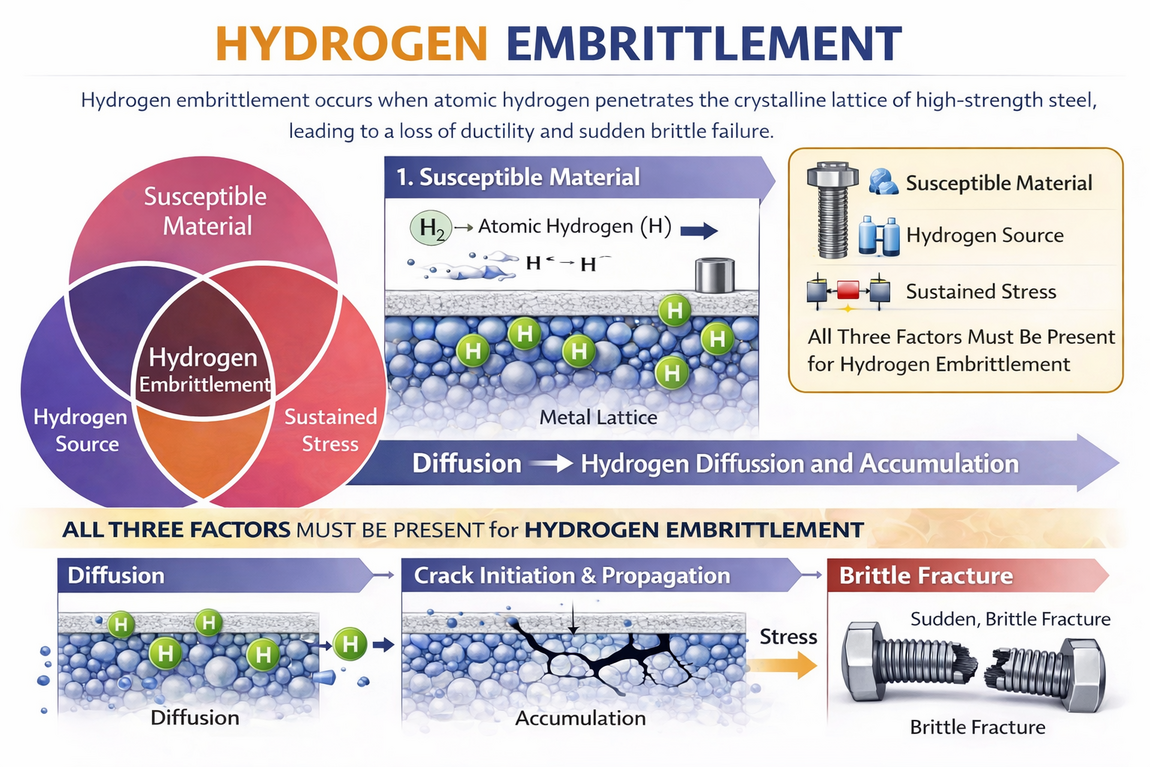
Hydrogen embrittlement (HE) is a metallurgical phenomenon in which atomic hydrogen penetrates the crystalline lattice of a metal, most commonly high-strength steel, causing a permanent and severe loss of ductility and load-bearing capacity that results in sudden, catastrophic brittle fracture at stress levels significantly below the material's specified yield strength.
Technical Detail and Definitions
Unlike a conventional mechanical overload, which produces visible stretching and necking before fracture, a hydrogen embrittlement failure is a delayed brittle fracture. The fastener may pass all installation torque checks and appear perfectly sound, then snap without warning hours, days, or even weeks later.
The phenomenon was first documented by William H. Johnson in 1875 at the Royal Society of London, making it one of the oldest known material degradation mechanisms in metallurgy.
Three simultaneous factors are required to produce hydrogen embrittlement failure:
- A susceptible material, typically a high-strength steel with hardness above 34-39 HRC.
- The presence of atomic (diffusible) hydrogen within the metal lattice.
- A sustained tensile stress, which may be an externally applied load or a residual stress from manufacturing, heat treatment, or installation torque.
If any one of these three factors is absent, hydrogen embrittlement failure will not occur.
Key definitions:
- Atomic Hydrogen (H): The smallest chemical element. Individual hydrogen atoms are small enough to migrate through the solid crystalline lattice of a metal. This is distinct from molecular hydrogen (H₂), which is a gas and cannot penetrate a solid metal surface at ambient temperatures.
- Crystalline Lattice: The highly ordered, repeating three-dimensional arrangement of atoms within a solid metal.
- Ductility: The ability of a material to undergo permanent plastic deformation under tensile stress (stretching) before fracturing.
- Brittle Fracture: A sudden failure characterised by a clean, flat break with little or no visible plastic deformation (necking or stretching) at the point of fracture.
- Yield Strength: The stress level at which a material transitions from elastic (reversible) deformation to permanent (irreversible) plastic deformation.
- Diffusible Hydrogen: Hydrogen atoms that are mobile within the metal lattice and free to migrate to areas of high stress, as opposed to hydrogen that is permanently locked in irreversible trap sites.
Hydrogen embrittlement is maximised at around room temperature in steels. Most metals are relatively immune to HE at temperatures above 150 degrees Celsius, because the elevated thermal energy increases hydrogen diffusion rates, allowing atoms to escape the lattice before concentrating at critical locations.
Source:
ISO/TR 20491:2019 - Fundamentals of hydrogen embrittlement in steel fasteners
ScienceDirect - Hydrogen trapping and embrittlement in metals
Wikipedia - Hydrogen Embrittlement
2. How does hydrogen move through steel at the atomic level?
Hydrogen atoms migrate through the spaces between iron atoms in the steel lattice via a process called interstitial diffusion, driven by concentration gradients and, critically, by mechanical stress fields within the component.
Technical Detail and Definitions
The movement of hydrogen within a metal is not random. Whilst there is a general tendency for atoms to diffuse from regions of high concentration to low concentration (Fick's Laws of Diffusion), the most dangerous aspect is stress-driven diffusion. Hydrogen atoms are physically pulled toward regions of high triaxial tensile stress within the fastener.
In a loaded bolt, the regions of highest tensile stress are:
- The root of the first engaged thread, where approximately 34% of the total load is concentrated.
- The fillet radius at the head-to-shank transition.
- Any surface discontinuity, scratch, tool mark, or corrosion pit that creates a local stress raiser.
This means that hydrogen atoms, once inside the steel, will migrate directly to the most dangerous location in the fastener: the exact point where a crack would be most likely to initiate.
Key definitions:
- Interstitial Diffusion: The movement of small solute atoms (like hydrogen, carbon, or nitrogen) through the spaces (interstices) between the larger solvent atoms (like iron) in a crystal structure.
- Body-Centred Cubic (BCC) Lattice: The crystal structure of ferritic and martensitic steels. This structure has relatively small interstitial sites but numerous pathways between them, allowing hydrogen to diffuse rapidly.
- Face-Centred Cubic (FCC) Lattice: The crystal structure of austenitic stainless steels and aluminium. This structure has larger interstitial sites that can hold more hydrogen, but the pathways between sites are more constricted.
The difference in crystal structure has a dramatic effect on diffusion speed:
- The diffusion coefficient of hydrogen in BCC iron at room temperature is approximately 10⁻⁻⁴ cm²/s.
- The diffusion coefficient of hydrogen in FCC iron (austenite) is approximately 10⁻⁻¹² cm²/s.
- This means hydrogen moves roughly 100 million times faster through ferritic/martensitic steels than through austenitic stainless steels.
- This fundamental difference in diffusion rate is a primary reason why austenitic stainless steels are generally far more resistant to hydrogen embrittlement.
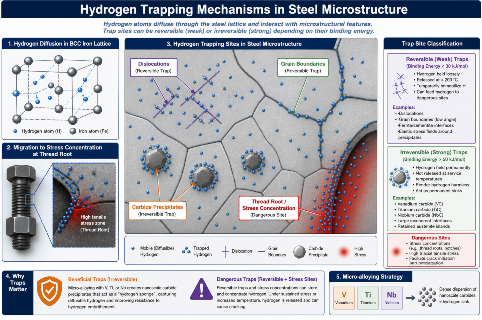
Trap sites within the microstructure:
- Reversible Traps: Sites where hydrogen can escape at relatively low temperatures. These include dislocations, small-angle grain boundaries, and elastic stress fields around precipitates.
- Irreversible Traps: Sites where hydrogen is permanently locked and rendered benign. These include certain carbide interfaces (e.g. vanadium carbides, titanium carbides) and large incoherent precipitate boundaries.
- Critical Concentration: The specific local volume of hydrogen required at a single trap site or grain boundary to initiate a micro-crack. This varies with material hardness, stress state, and temperature.
At baking temperatures (190 to 230 degrees Celsius), the diffusion rate increases by several orders of magnitude, allowing trapped hydrogen to migrate outward through the metal surface. This is the fundamental principle behind post-plating hydrogen embrittlement relief baking.
Source:
Oxford University - Hydrogen Embrittlement Research
Nature - Hydrogen in Materials Collection
ISO/TR 20491:2019
3. What is the difference between Internal and Environmental Hydrogen Embrittlement?
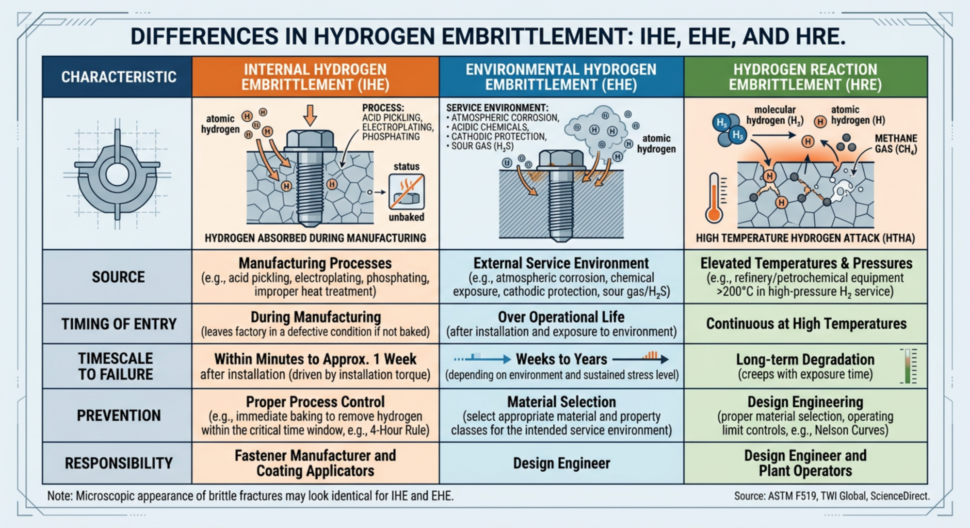
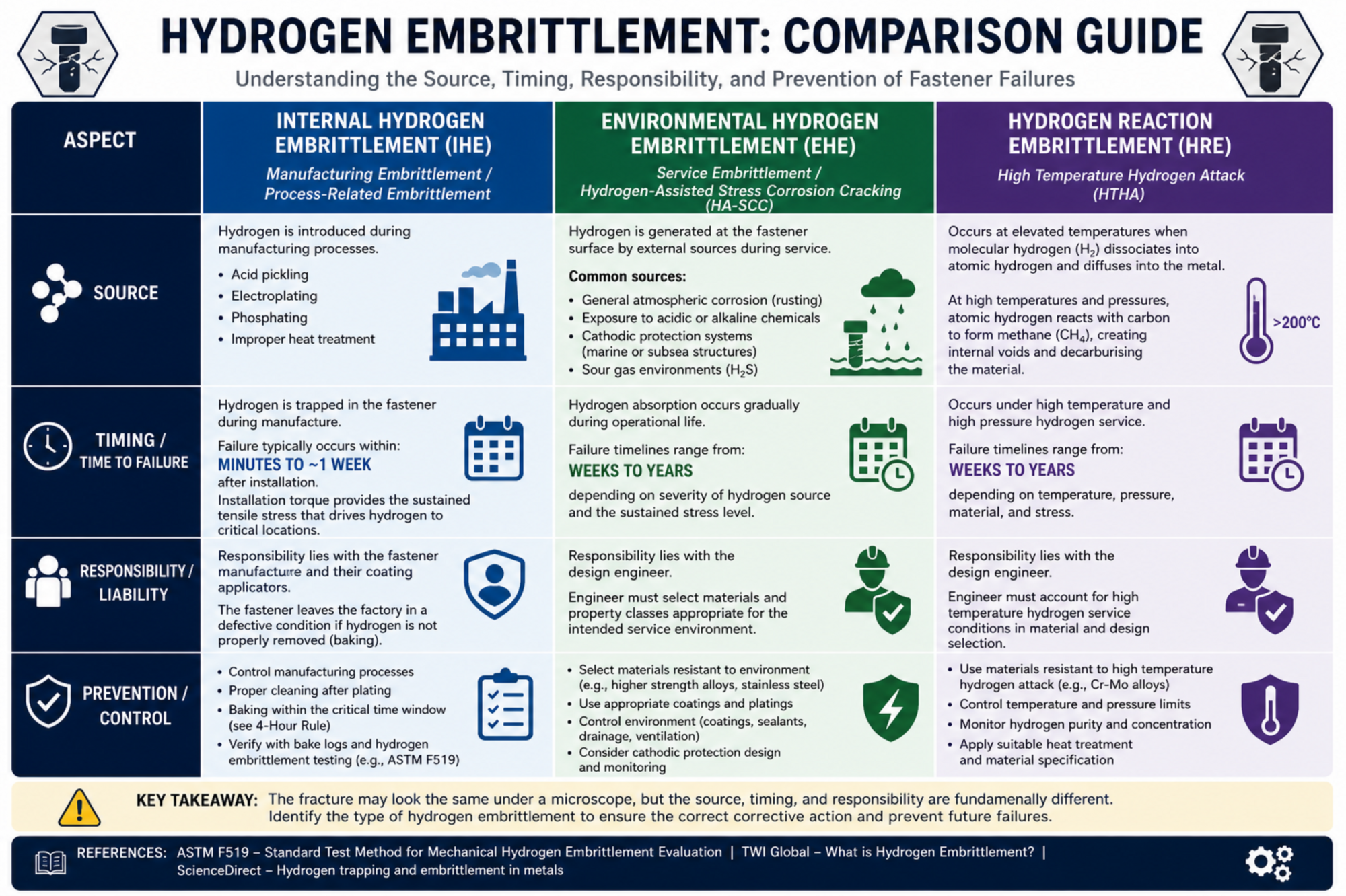
The distinction lies entirely in the source and timing of hydrogen entry into the fastener. Internal Hydrogen Embrittlement (IHE) results from hydrogen absorbed during manufacturing processes. Environmental Hydrogen Embrittlement (EHE) occurs when a clean, properly manufactured fastener absorbs hydrogen from its service environment over time.
Technical Detail and Definitions
Although the resulting brittle fracture may appear identical under microscopic examination, the prevention strategies, timescales, and liability frameworks for IHE and EHE are fundamentally different.
Internal Hydrogen Embrittlement (IHE): Also known as Manufacturing Embrittlement or Process-Related Embrittlement.
- Hydrogen is introduced during production operations such as acid pickling, electroplating, phosphating, or improper heat treatment.
- If this manufacturing hydrogen is not removed via baking within the critical time window (see the 4-Hour Rule, Question 54), the fastener leaves the factory in a defective condition.
- Failure typically occurs within minutes to approximately one week after installation.
- The installation torque provides the sustained tensile stress that drives hydrogen to critical locations.
- IHE is entirely preventable through proper manufacturing process control.
Responsibility lies with the fastener manufacturer and their coating applicators.
Environmental Hydrogen Embrittlement (EHE): Also known as Service Embrittlement or Hydrogen-Assisted Stress Corrosion Cracking (HA-SCC). Hydrogen is generated at the fastener surface by external sources during its operational life.
- Common sources include:
- General atmospheric corrosion (rusting).
- Exposure to acidic or alkaline chemicals.
- Cathodic protection systems used on marine or subsea structures.
- Exposure to sour gas environments containing hydrogen sulphide (H₂S).
- Failure timelines range from weeks to years, depending on severity of the hydrogen source and the sustained stress level.
- Responsibility lies with the design engineer, who must select materials and property classes appropriate for the intended service environment.
Hydrogen Reaction Embrittlement (HRE): A third, less common classification.
- Occurs at elevated temperatures when molecular hydrogen (H₂) dissociates into atomic form and diffuses into the metal.
- At high temperatures and pressures, atomic hydrogen can react with carbon in the steel to form methane (CH₄), which creates internal voids and decarburises the material.
- Sometimes called High Temperature Hydrogen Attack (HTHA).
- Primarily a concern in refinery and petrochemical equipment operating above 200 degrees Celsius in high-pressure hydrogen service.
Source:
ASTM F519 - Standard Test Method for Mechanical Hydrogen Embrittlement Evaluation
TWI Global - What is Hydrogen Embrittlement?
ScienceDirect - Hydrogen trapping and embrittlement in metals
flowchart LR
    Root["Hydrogen Embrittlement (HE)"]
    Root --> IHE["Internal Hydrogen Embrittlement (IHE)"]
    Root --> EHE["Environmental Hydrogen Embrittlement (EHE)"]
    Root --> HRE["Hydrogen Reaction Embrittlement (HRE)"]

    IHE --> IHE1["Manufacturing or Process-Related"]
    IHE --> IHE2["Source: Production (Pickling, Plating, Heat Treatment)"]
    IHE --> IHE3["Timing: Minutes to ~1 week post-installation"]
    IHE --> IHE4["Liability: Manufacturer / Coating Applicator"]
    IHE --> IHE5["Prevention: Proper process control & 4-Hour Baking Rule"]

    EHE --> EHE1["Service Embrittlement or HA-SCC"]
    EHE --> EHE2["Source: Service Environment (Rust, Acids, Cathodic Protection, H₂S)"]
    EHE --> EHE3["Timing: Weeks to years"]
    EHE --> EHE4["Liability: Design Engineer"]
    EHE --> EHE5["Prevention: Appropriate material & property class selection"]

    HRE --> HRE1["High Temperature Hydrogen Attack (HTHA)"]
    HRE --> HRE2["Source: Dissociated H₂ reacting with Carbon → Methane (CH₄) voids"]
    HRE --> HRE3["Timing: Long-term high temp/pressure exposure"]
    HRE --> HRE4["Liability: Plant/Process Engineering"]
    HRE --> HRE5["Environment: Petrochemical equipment > 200°C"]

    style Root fill:#e8e8e8,stroke:#000,stroke-width:3px,font-weight:bold,color:#000
    style IHE fill:#ff6b6b,stroke:#000,stroke-width:2px,font-weight:bold,color:#000
    style EHE fill:#4da6ff,stroke:#000,stroke-width:2px,font-weight:bold,color:#000
    style HRE fill:#66cc33,stroke:#000,stroke-width:2px,font-weight:bold,color:#000
4. What are the primary mechanisms by which hydrogen causes embrittlement?
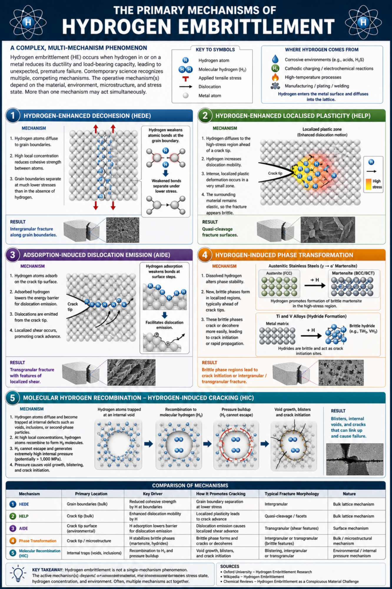
There is no single universally accepted mechanism. Contemporary metallurgical science recognises at least four competing theories, each of which explains certain aspects of observed behaviour. It is now widely accepted that hydrogen embrittlement is a complex, material-dependent process in which no single mechanism applies exclusively.
Technical Detail and Definitions
The four principal mechanisms proposed in the literature are:
1. Hydrogen-Enhanced Decohesion (HEDE):
- Proposes that hydrogen atoms concentrated at grain boundaries reduce the cohesive strength of atomic bonds.
- This weakening makes it easier for grain boundaries to separate at stress levels far below the material's normal fracture strength.
- HEDE can only occur when the local concentration of hydrogen is high, such as in the tensile stress field at a crack tip or at stress concentrators.
- This mechanism best explains the characteristic intergranular fracture morphology seen in many hydrogen embrittlement failures.
2. Hydrogen-Enhanced Localised Plasticity (HELP):
- Proposes that dissolved hydrogen increases the mobility of dislocations (the line defects responsible for plastic deformation) at a crack tip.
- This creates intense, localised plastic deformation zones directly ahead of the crack.
- The surrounding material remains undeformed, giving the fracture a macroscopically brittle appearance despite being microscopically ductile at the crack tip.
- This mechanism best explains the quasi-cleavage fracture surfaces sometimes observed.
3. Adsorption-Induced Dislocation Emission (AIDE):
- Proposes that hydrogen adsorbed on the crack tip surface facilitates the emission of dislocations from the crack tip.
- This promotes crack advance by localised shear processes at the crack tip.
- AIDE is considered an environmental surface mechanism, in contrast to the bulk lattice mechanisms of HEDE and HELP.
4. Hydrogen-Induced Phase Transformation:
- In some materials, dissolved hydrogen can stabilise brittle phases within the microstructure.
- For example, in austenitic stainless steels, hydrogen can promote the transformation of austenite (FCC) to martensite (BCC or BCT) at crack tips, creating a locally brittle zone.
- In titanium and vanadium alloys, hydrogen forms brittle metallic hydrides (e.g. TiH₂) that act as crack initiation sites.
Additionally, molecular recombination plays a role:
- Hydrogen atoms may recombine into molecular form (H₂) at internal voids, inclusions, or other discontinuities.
- The molecular hydrogen cannot escape and generates enormous internal pressures (potentially exceeding 1,000 MPa).
- This creates blisters, voids, and crack initiation sites, a process sometimes called Hydrogen-Induced Cracking (HIC).
Source:
Oxford University - Hydrogen Embrittlement Research
Wikipedia - Hydrogen Embrittlement
Chemical Reviews - Hydrogen Embrittlement as a Conspicuous Material Challenge
5. What are trap sites and why are they important?
Trap sites are specific metallurgical features within the steel microstructure where hydrogen atoms accumulate because the local energy state is lower than in the surrounding lattice. Trap sites can be either beneficial (rendering hydrogen harmless) or dangerous (concentrating hydrogen at vulnerable locations), depending on their type and location.
Technical Detail and Definitions
Not all hydrogen in steel is dangerous. The key distinction is between mobile (diffusible) hydrogen and trapped hydrogen:
Reversible (Weak) Traps:
- These sites hold hydrogen loosely, with a low binding energy (typically below 30 kJ/mol).
- Hydrogen can escape from reversible traps at modest temperatures (below 200 degrees Celsius).
- Examples include:
- Dislocations (line defects in the crystal structure).
- Small-angle grain boundaries.
- Elastic stress fields around coherent precipitates.
- Ferrite/cementite interfaces.
- Reversible traps are dangerous because they temporarily hold hydrogen but release it under increased temperature or sustained stress, feeding mobile hydrogen to crack initiation sites.
Irreversible (Strong) Traps:
- These sites hold hydrogen permanently, with a high binding energy (typically above 50 kJ/mol).
- Hydrogen cannot escape at service temperatures and is rendered harmless.
- Examples include:
- Vanadium carbide (VC) precipitates, binding energy approximately 35-55 kJ/mol.
- Titanium carbide (TiC) precipitates, binding energy approximately 55-95 kJ/mol.
- Niobium carbide (NbC) precipitates.
- Large incoherent precipitate/matrix interfaces.
- Retained austenite islands (in mixed-phase steels).
- Irreversible traps are beneficial because they act as hydrogen sinks, permanently removing diffusible hydrogen from the lattice.
Modern micro-alloying strategies:
- Research at the University of Manchester and other institutions has demonstrated that adding trace amounts of vanadium, titanium, or niobium to fastener steels can create a dense dispersion of nanoscale carbide precipitates.
- These precipitates act as a hydrogen "sponge," soaking up diffusible hydrogen before it can reach grain boundaries.
- This allows the design of higher-strength fasteners with improved resistance to hydrogen embrittlement.
- The concept is being applied to the newest generation of high-strength fastener steels for automotive and aerospace applications.
Source:
University of Manchester - Role of precipitates in hydrogen trapping
Nature - Hydrogen in Materials
ScienceDirect - Hydrogen trapping and embrittlement in metals
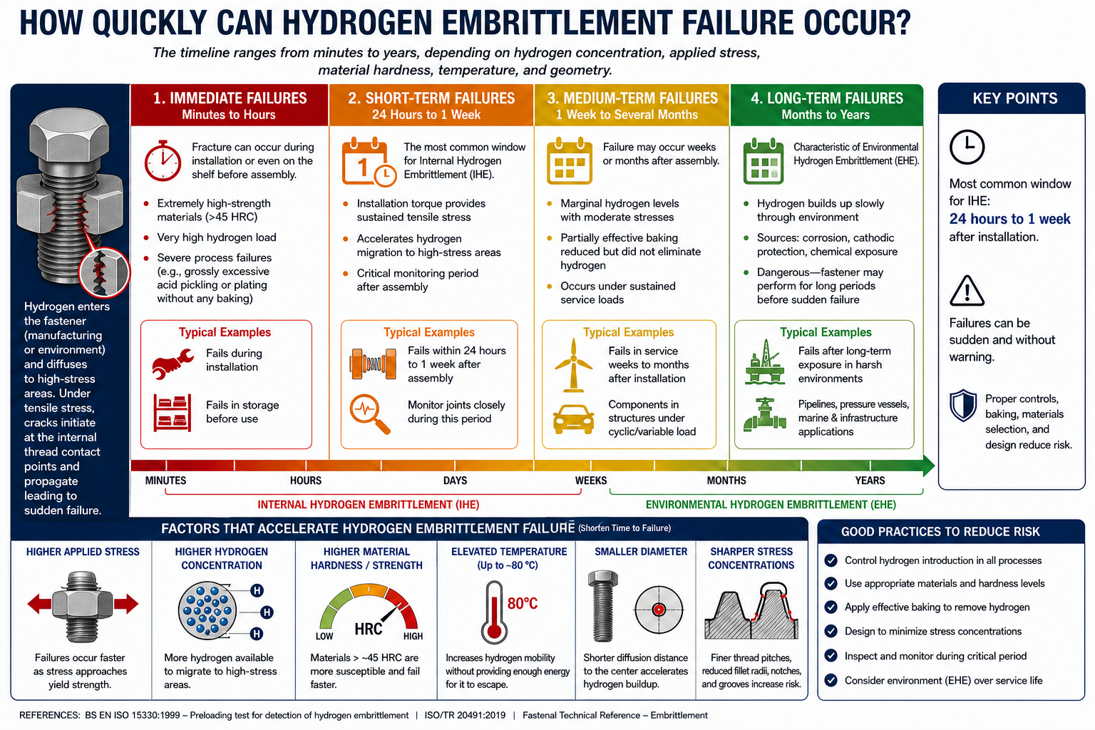
6. How quickly can hydrogen embrittlement failure occur?
The timeline for hydrogen embrittlement failure varies from minutes to years, depending on hydrogen concentration, applied stress, material hardness, and temperature. The most common window for manufacturing-related failure (IHE) is 24 hours to one week after installation.
Technical Detail and Definitions
The delay between hydrogen absorption and fracture is the time required for hydrogen atoms to migrate to the point of highest stress and reach critical concentration. This depends on multiple interacting factors:
Immediate Failures (Minutes to Hours):
- Seen in extremely high-strength materials (above 45 HRC) with very high hydrogen loads.
- Typically associated with severe process failures such as grossly excessive acid pickling or electroplating without any subsequent baking.
- Parts may fracture during installation or on the shelf before assembly.
Short-Term Failures (24 Hours to 1 Week):
- The most common window for Internal Hydrogen Embrittlement.
- The installation torque provides the sustained tensile stress that accelerates hydrogen migration.
- This is the critical monitoring period after assembly of high-strength fastener joints.
Medium-Term Failures (1 Week to Several Months):
- May result from marginal hydrogen levels combined with moderate stresses.
- Can also result from partially effective baking that reduced but did not eliminate absorbed hydrogen.
Long-Term Failures (Months to Years):
- Characteristic of Environmental Hydrogen Embrittlement (EHE).
- Hydrogen builds up slowly through corrosion, cathodic protection, or chemical exposure.
- Particularly dangerous because the fastener may have performed satisfactorily for extended periods before sudden failure.
Factors that accelerate failure:
- Higher applied stress levels (failures occur faster closer to yield strength).
- Higher hydrogen concentration in the material.
- Higher material hardness and strength.
- Elevated temperature (up to approximately 80 degrees Celsius, which increases hydrogen mobility without providing enough energy for hydrogen to escape).
- Smaller fastener diameter (shorter diffusion distance to the centre).
- Sharper stress concentrations (finer thread pitches, reduced fillet radii).
Source:
BS EN ISO 15330:1999 - Preloading test for detection of hydrogen embrittlement
ISO/TR 20491:2019
Fastenal Technical Reference - Embrittlement
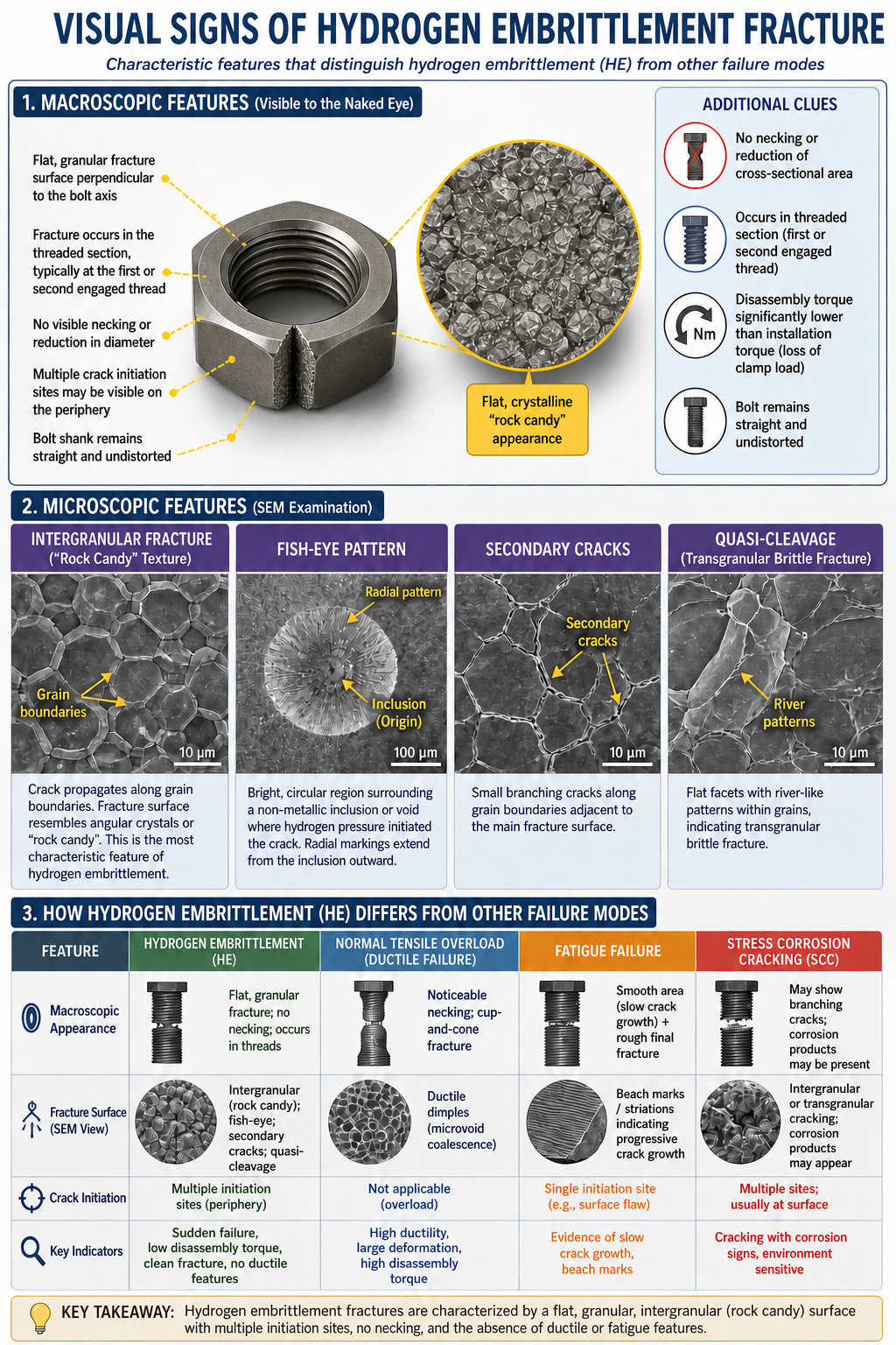
7. What are the characteristic visual signs of a hydrogen embrittlement fracture?
A hydrogen embrittlement fracture displays a brittle, intergranular or quasi-cleavage fracture surface with little or no visible plastic deformation. The bolt shows no necking, no reduction in diameter, and no stretching. Fractures typically initiate at the thread root and display a flat, granular, crystalline appearance distinctly different from normal ductile failure.
Metallurgical laboratories use optical microscopy and Scanning Electron Microscopy (SEM) to confirm the failure mode. The characteristic features are:
Macroscopic Features (Visible to the Naked Eye):
- No visible necking or reduction of cross-sectional area at the fracture location.
- Flat, granular fracture surface perpendicular to the bolt axis.
- The fracture typically occurs in the threaded section, most commonly at the first or second engaged thread.
- Multiple crack initiation sites may be visible on the fracture periphery.
- The bolt shank remains straight and undistorted.
- Disassembly torque may be significantly lower than the original installation torque, indicating loss of clamp load.
Microscopic Features (SEM Examination):
- Intergranular Fracture: The crack follows the grain boundaries, producing a fracture surface that resembles a collection of angular crystals or "rock candy." This is the most characteristic feature of hydrogen embrittlement.
- Quasi-Cleavage: In some cases, the fracture surface shows flat facets with river-like patterns within individual grains, indicating transgranular brittle fracture.
- Fish-Eye Patterns: Bright, circular patches surrounding non-metallic inclusions or internal voids where hydrogen pressure initiated the crack. Under SEM, the fish-eye shows a distinct radial pattern emanating from the inclusion at its centre.
- Secondary Cracking: Small branching cracks adjacent to the main fracture surface, following grain boundaries.
- Absence of Fatigue Striations: Unlike fatigue failures, which show progressive beach marks or striations, hydrogen embrittlement fractures appear sudden and complete.
How HE Fracture Differs from Other Failure Modes:
- Normal Tensile Overload: Shows visible necking, cup-and-cone fracture surface, ductile dimples under SEM.
- Fatigue Failure: Shows beach marks, striations, progressive crack growth from a single initiation point, smooth fracture surface in the fatigue zone.
- Stress Corrosion Cracking (SCC): May show branching cracks, corrosion products on fracture surfaces, and can be intergranular or transgranular depending on alloy and environment.
- Hydrogen Embrittlement: Clean intergranular fracture with no corrosion products, no beach marks, no ductile features, and typically multiple initiation sites.
Source:
Infinita Lab - Fastener Failure Analysis Testing
ScienceDirect - Fractography of Hydrogen Embrittlement
8. What is the "threshold stress" for hydrogen embrittlement?
The threshold stress is the minimum sustained tensile stress below which hydrogen embrittlement failure will not occur for a given material, hydrogen concentration, and temperature. It is typically expressed as a percentage of the material's yield strength or as an absolute stress value in megapascals..
Technical Detail and Definitions
The threshold stress concept is fundamental to both engineering design and testing:
- For a given steel, as hydrogen concentration increases, the threshold stress decreases.
- For a given hydrogen concentration, as material hardness increases, the threshold stress decreases.
(see the arbitrary lines on the image below)
- The threshold stress for a susceptible, hydrogen-charged Class 12.9 fastener may be as low as 40-60% of its specified yield strength.
- For a Class 10.9 fastener with the same hydrogen charge, the threshold stress is typically higher, often 60-80% of yield strength.
- For materials below 34 HRC (approximately 320HV / Property class 8.8 or 8), the threshold stress is often close to or above the yield strength, meaning hydrogen embrittlement failure becomes practically impossible under normal service loads because the ductile matrix can accommodate the hydrogen without initiating micro-cracks.
How Threshold Stress is Measured:
- ASTM F1624 (Incremental Step Loading): The primary quantitative method used to determine these values. The applied load is increased in precise, small steps with specific holding periods to plot the exact point where subcritical crack growth initiates.
- ASTM F519 (Sustained Load Testing): A standard pass/fail compliance test rather than a quantitative measurement. Fasteners are typically clamped or loaded to 75% or 80% of their yield strength and held for 200 hours to verify that the threshold stress remains safely above the intended service load.
The Embrittlement Ratio and Industry Origins:
- Defined as the threshold stress of the hydrogen-charged specimen divided by the baseline strength of an uncharged specimen.
- Expressed as a decimal or percentage (e.g. 0.75 or 75%).
These baseline values are established empirically through extensive statistical testing by global standards organizations (such as ASTM and ISO) to build in real-world safety margins against commercial batch variances.
- Typical acceptance criteria:
- General applications: embrittlement ratio above 0.60 (60%). This standard margin ensures that regular structural safety factors naturally prevent the joint from approaching the fracture danger zone.
- Critical applications: embrittlement ratio above 0.75 (75%).
- Aerospace applications: embrittlement ratio above 0.80 (80%). Mandated by strict regulatory frameworks (such as SAE AMS specifications) where dynamic fatiguing or environmental corrosion might introduce hydrogen over time.
- An embrittlement ratio of 1.00 (100%) would indicate zero susceptibility.
Source:
ASTM F1624 - Measurement of Hydrogen Embrittlement Threshold in Steel
ASTM F519 - Standard Test Method for Mechanical Hydrogen Embrittlement Evaluation
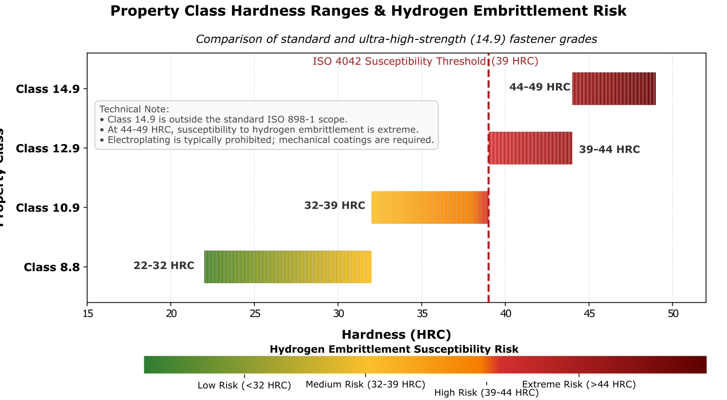
Understanding the Hydrogen Embrittlement Threshold Chart
This chart illustrates how trapped hydrogen drastically reduces the load-bearing capability of high-tensile steel fasteners under sustained tension. Rather than using an arbitrary mathematical formula, these curves map real-world empirical data derived from standardized metallurgical testing (such as ASTM F1624 incremental step loading).
Key Components of the Graph
- The Vertical Axis (Applied Tensile Stress): This tracks the Embrittlement Ratio, which is the percentage of the fastener's original, uncharged yield strength. A clean, hydrogen-free bolt starts at 100% capacity on the far left.
- The Horizontal Axis (Hydrogen Concentration): This tracks the volume of atomic hydrogen trapped within the steel lattice, typically introduced during chemical acid pickling or electroplating.
The Material Curve Trajectories:
- Low Hardness / < 34 HRC (Green Line): Lower-strength grades (such as Property Class 8.8) possess high fracture toughness. The ductile steel matrix deforms plastically around hydrogen atoms without cracking, keeping its threshold stress near 100%.
- Class 10.9 Fasteners (Blue Line): High-tensile fasteners exhibit moderate susceptibility. As hydrogen levels increase, the threshold stress drops significantly before stabilizing at a plateau between 60% and 70% of yield strength.
- Class 12.9 Fasteners (Red Line): Extreme-hardness fasteners possess low fracture toughness. Even minuscule amounts of hydrogen cause a catastrophic drop, plummeting the safe threshold stress to between 40% and 50% of the material's yield strength.
The Standardised Minimum Lines
The horizontal dashed lines represent the regulatory pass/fail boundaries established by global engineering standards (such as ASTM F519 and ISO 15330) to manage structural risk:
- General Minimum (60%): The absolute lower bound allowed for standard commercial and structural applications.
- Critical Minimum (75%): The safety threshold mandated for high-consequence industrial joints.
- Aerospace Minimum (80%): The tightest regulatory boundary, mandated because aerospace fasteners operate under severe fatigue and high preloads where any drop in material capability poses a catastrophic safety risk.
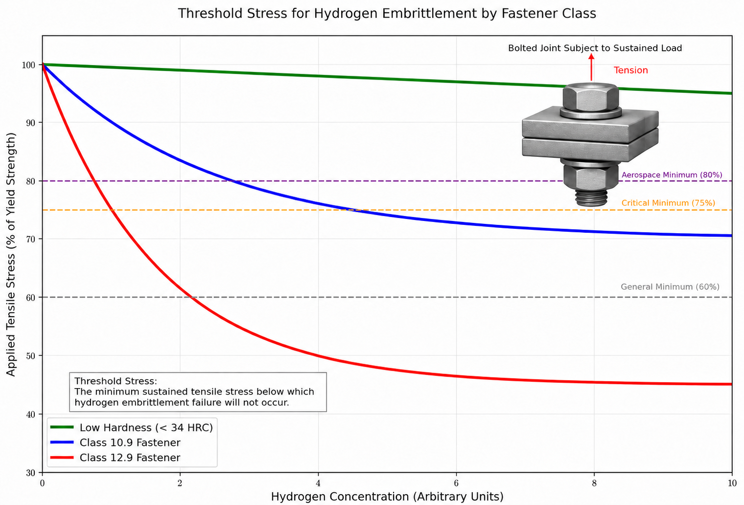
Please note these are arbitrary values.
9. What is the role of residual stress in hydrogen embrittlement?
Residual stresses are internal stresses that exist within a component even when no external load is applied. They are extremely significant in hydrogen embrittlement because they can provide the sustained tensile stress component required for failure, meaning a fastener can fail "on the shelf" without ever being installed.
Technical Detail and Definitions
Residual stresses in fasteners originate from multiple manufacturing operations:
Sources of Residual Stress:
- Cold Forming: Heading, thread rolling, and cold forging introduce significant residual stress patterns.
- Heat Treatment: Quenching creates thermal gradients that produce residual stresses. Tempering partially relieves these, but some always remain.
- Machining and Grinding: Surface material removal can leave tensile residual stresses in the surface layer.
- Electroplating: The plating deposit itself can be highly stressed, creating tensile residual stresses at the steel/coating interface.
- Surface Hardening: Case hardening, nitriding, and carburising create significant stress gradients at the case-core boundary.
Why Residual Stress Matters:
- A fastener with high tensile residual stress at its surface can exceed the hydrogen embrittlement threshold stress without any externally applied load.
- This explains the phenomenon of "shelf cracking" or "popping on the shelf," where electroplated fasteners fracture whilst sitting in storage bins.
- Thread rolling after heat treatment (post-hardening rolling) introduces compressive residual stress at the thread root, which is beneficial for fatigue life but creates corresponding tensile residual stress subsurface, which can accelerate hydrogen migration.
- The total effective stress for hydrogen embrittlement purposes is the sum of applied stress plus residual stress.
Mitigation Strategies:
- Ensure adequate tempering after quench hardening to relieve the maximum amount of residual stress.
- Prefer thread rolling before heat treatment for susceptible materials to minimise residual stresses in the final product.
- Shot peening after heat treatment can introduce beneficial compressive residual stress at the surface, potentially raising the effective threshold stress.
- Stress relief treatments at temperatures below the tempering temperature can reduce residual stresses without affecting mechanical properties.
Source:
ISO/TR 20491:2019
DST Chemicals - Knowledge on Hydrogen Embrittlement
10. What is the relationship between hydrogen fugacity and embrittlement severity?
Fugacity is a thermodynamic measure of the effective "pressure" or "activity" of hydrogen at a metal surface, accounting for the non-ideal behaviour of hydrogen gas at high pressures. Higher fugacity means a greater driving force for hydrogen to enter the metal, and therefore a greater embrittlement risk.
Technical Detail and Definitions
Understanding fugacity is essential for engineers designing equipment for the hydrogen economy and high-pressure gas service:
- At low pressures, hydrogen gas behaves close to an ideal gas, and fugacity is approximately equal to pressure.
- At elevated pressures (above approximately 10 MPa), hydrogen deviates significantly from ideal gas behaviour, and fugacity can be substantially higher than the actual pressure.
- For example, at 70 MPa (700 bar, typical of hydrogen fuel cell vehicle storage tanks), the fugacity of hydrogen is approximately 100-120 MPa.
- This means the thermodynamic driving force for hydrogen entry is 40-70% greater than the actual tank pressure would suggest.
Relevance to Fastener Applications:
- Bolted flanges on high-pressure hydrogen pipelines, storage vessels, and refuelling equipment experience hydrogen fugacity directly at the bolt surface.
- Even if the fastener material is below the traditional 39 HRC susceptibility threshold, the enhanced hydrogen activity at high fugacity can push lower-strength materials toward their embrittlement limits.
- ASME B31.12 (Hydrogen Piping and Pipelines) and other hydrogen-economy standards are developing material performance factors that account for fugacity-dependent embrittlement.
Electrochemical Fugacity:
- Hydrogen generated electrochemically (e.g. during electroplating, acid corrosion, or cathodic protection) can have an equivalent fugacity of thousands of megapascals.
- This explains why a simple acid pickling bath can introduce more aggressive hydrogen charging than a 700 bar pressure vessel.
- The presence of "poisons" such as hydrogen sulphide (H2S), arsenic, phosphorus, or thiourea on the metal surface dramatically increases the electrochemical fugacity by preventing hydrogen atoms from recombining into harmless molecular hydrogen (H2) gas.
Source:
H2Tools - Material Compatibility
ScienceDirect - Hydrogen trapping and embrittlement in metals
Greene Tweed - Hydrogen Power Solutions
Section 2: Susceptible Materials
11. Which materials are susceptible to hydrogen embrittlement?
Susceptibility is primarily a function of the material's hardness, strength, and crystal structure. High-strength carbon and alloy steels with hardness above 39 HRC are at highest risk. However, hydrogen embrittlement is not limited to steels; it affects a broad range of metals and alloys to varying degrees.
Technical Detail and Definitions
The following table summarises the susceptibility of major material groups:
| Material Group | Susceptibility Level | Primary Risk Factors | Key Mitigants |
|---|---|---|---|
| Carbon and Alloy Steels (above 39 HRC) | Extreme | High hardness, martensitic structure, internal stress | Immediate post-plating baking (8-24 hours), mechanical cleaning |
| Case-Hardened Steels | Very High | Hard surface case (above 45 HRC) regardless of core | Strict case depth control, mandatory baking |
| Spring Steels | Very High | Extreme hardness (50-60 HRC) and stored elastic energy | Extreme hardness (50-60 HRC) and stored elastic energy |
| Carbon and Alloy Steels (34-39 HRC) | High | Transitional range, process control critical | Precautionary baking, controlled pickling |
| Martensitic Stainless Steels (400 Series) | High | Heat-treated to high strength, BCC structure | Avoid electroplating, prefer organic or mechanical coatings |
| Precipitation-Hardened Stainless Steels (e.g. 17-4 PH) | High | Ageing at low temperatures creates high susceptibility | Use higher ageing temperatures (e.g. H1150 condition) |
| Duplex Stainless Steels | Moderate | Ferritic phase susceptible, austenitic phase resistant | Control ferrite content, avoid cathodic overprotection |
| High-Strength Aluminium Alloys (2xxx, 7xxx) | Moderate | Susceptible at high temperatures and when cold-worked | Microstructural control, barrier coatings |
| Titanium Alloys | Moderate | Form brittle hydrides (TiH₂) above critical concentrations | Control hydrogen exposure, avoid cathodic charging |
| Austenitic Stainless Steels (300 Series) | Low | FCC structure, very slow hydrogen diffusion | Resistant unless heavily cold-worked or sensitised |
| Carbon and Alloy Steels (below 34 HRC) | Low | Generally resistant at these hardness levels | Standard manufacturing processes adequate |
| Nickel Alloys (Inconel, K-Monel) | Low to Moderate | Generally resistant but affected at very high pressures | Generally resistant but affected at very high pressures |
| Copper and Brass | Very Low | Generally immune to classical HE | Susceptible only as oxygen-bearing copper (Cu₂O reduction) |
| Bronze (PB102, CA104, NES833) | Very Low | Not susceptible to hydrogen embrittlement | No special precautions required |
Source:
BS EN ISO 898-1 - Mechanical properties of fasteners
Wikipedia - Hydrogen Embrittlement
NASA/TM-2016-218602 - Hydrogen Embrittlement
12. Why is bolt Property Class 12.9 the most vulnerable fastener grade?
Property Class 12.9 bolts per ISO 898-1 represent the extreme limit of carbon and alloy steel strength for standard threaded fasteners, with a specified hardness range of 39-44 HRC (385-435 HV). At this level, the steel lattice is so tightly stressed that it has virtually zero tolerance for the presence of atomic hydrogen.
Technical Detail and Definitions
- The minimum tensile strength for Class 12.9 is 1220 MPa, with a minimum yield strength (proof stress) of 1100 MPa.
- The hardness range of 39-44 HRC places these fasteners squarely in the "extreme risk" zone identified by ISO 4042, ASTM F1941, and industry consensus.
- ISO 898-1 itself contains an explicit warning that Class 12.9 fasteners are susceptible to stress corrosion cracking (including hydrogen-assisted SCC) and should be used with extreme caution in corrosive environments.
Why 12.9 is more vulnerable than 10.9:
- The threshold hydrogen concentration required to initiate failure decreases exponentially as hardness increases.
- A Class 10.9 bolt (hardness 32-39 HRC) might tolerate several parts per million of diffusible hydrogen before crack initiation.
- A Class 12.9 bolt can fail with trace amounts of hydrogen, sometimes as little as 0.5-1.0 ppm of diffusible hydrogen.
- The elevated residual stresses from quench-and-temper heat treatment at these high hardness levels create more favourable conditions for hydrogen migration.
Environmental sensitivity:
- Class 12.9 fasteners can fail from Environmental Hydrogen Embrittlement even in mildly damp or condensing atmospheric conditions without any electroplating being present.
- Road salt, industrial atmospheres, and even high-humidity storage conditions can generate sufficient hydrogen through surface corrosion to trigger failure.
Industry response:
- Many safety-critical specifications (particularly automotive and aerospace) are moving away from Class 12.9 in favour of Class 10.9 at larger diameters to achieve equivalent joint capacity at lower susceptibility.
- Where Class 12.9 is unavoidable, non-electrolytic coating systems (zinc flake, mechanical galvanising, organic coatings) are strongly preferred over electroplating.
- Post-plating baking for Class 12.9 is typically specified at 24 hours minimum, compared to 8 hours for Class 10.9.
Source:
Fasto Screws - Why High Strength Grade 12.9 Bolts Fail
BS EN ISO 898-1 - Mechanical properties of fasteners
ISO 4042:2022 - Fasteners. Electroplated coating systems
13. What is the hydrogen embrittlement risk for high-strength nuts (Grade 10 and Grade 12)?
The distinction between bolt property classes and nut property classes is critical. Nuts are graded differently from bolts: nut Grades 10 and 12 per ISO 898-2 are the high-strength equivalents that pair with bolt Classes 10.9 and 12.9 respectively. Nuts above Grade 8 that are electroplated should be treated as susceptible to hydrogen embrittlement and de-embrittled after plating.
Technical Detail and Definitions
- Bolt property classes use a two-number system (e.g. 8.8, 10.9, 12.9) where the first number indicates one-hundredth of the minimum tensile strength in MPa and the second indicates the yield-to-tensile ratio.
- Nut property classes use a single-number system (e.g. 5, 6, 8, 10, 12) which indicates the bolt property class with which the nut is designed to be matched.
- A Grade 10 nut is designed to be used with a Class 10.9 bolt; a Grade 12 nut is designed to be used with a Class 12.9 bolt.
Hydrogen embrittlement risk in nuts:
- The hardness of Grade 10 nuts typically ranges from 26-36 HRC depending on size.
- The hardness of Grade 12 nuts typically ranges from 32-38 HRC.
- Whilst these hardness values are generally lower than the corresponding bolt classes, any nut above Grade 8 (approximately 30 HRC and above) should be considered potentially susceptible, particularly:
- Nuts at the upper end of their hardness range.
- Smaller diameter nuts (which have higher surface-to-volume ratios and absorb hydrogen faster).
- Nuts that have been electroplated without subsequent baking.
De-embrittlement requirements:
- Electroplated Grade 10 and Grade 12 nuts should receive the same post-plating hydrogen relief baking as the corresponding bolt grades.
- Grade 10 nuts: minimum 8 hours at 190-230 degrees Celsius, commencing within 4 hours of plating.
- Grade 12 nuts: minimum 8-24 hours at 190-230 degrees Celsius, commencing within 4 hours of plating.
- Non-electrolytic coatings (zinc flake, sherardising, mechanical galvanising) eliminate this requirement.
Source:
BS EN ISO 898-2 - Mechanical properties of fasteners. Nuts
ISO 4042:2022 - Fasteners. Electroplated coating systems
14. Are Class 10.9 fasteners safer than Class 12.9 regarding hydrogen embrittlement?
- Yes, significantly. Class 10.9 fasteners have a lower hardness range (32-39 HRC) which provides substantially greater tolerance for hydrogen before crack initiation. For many safety-critical applications, specifying Class 10.9 at a larger diameter rather than Class 12.9 at a smaller diameter is the single most effective hydrogen embrittlement risk reduction strategy available.
Technical Detail and Definitions
- Class 10.9 fasteners have a minimum tensile strength of 1040 MPa and a proof stress of 940 MPa.
- The hardness range of 32-39 HRC places Class 10.9 in the transitional susceptibility zone, where careful manufacturing process control provides adequate protection.
- The slightly more open, lower-energy lattice of Class 10.9 steel tolerates more internal hydrogen before reaching the critical concentration for crack initiation.
Quantitative comparison:
- The threshold stress (as a percentage of yield strength) for Class 10.9 is typically 60-85%, depending on hydrogen concentration.
- The threshold stress for Class 12.9 under the same hydrogen conditions is typically 40-65%.
- This means a Class 10.9 bolt can safely carry a higher proportion of its rated load in the presence of hydrogen.
Field reliability data:
- In automotive applications, Class 10.9 is strongly preferred for safety-critical chassis and suspension fasteners.
- The combination of adequate strength, manageable hydrogen embrittlement risk, and good resistance to environmental stress corrosion cracking makes Class 10.9 the "workhorse" grade of modern engineering.
- Class 12.9 is typically reserved for applications where space constraints absolutely prevent the use of a larger-diameter 10.9 alternative.
Source:
BS EN ISO 898-1 - Mechanical properties of fasteners
Fasto Screws - Why High Strength Grade 12.9 Bolts Fail
15. What about Property Class 14.9 and above?
Property Class 14.9 fasteners, with a minimum tensile strength of 1400 MPa and hardness of 44-49 HRC, represent ultra-high-strength applications that are almost exclusively confined to aerospace and specialist engineering. These fasteners are at the absolute maximum risk for hydrogen embrittlement and require the most rigorous controls of any standard fastener grade.
Technical Detail and Definitions
- Class 14.9 is not covered by the standard ISO 898-1 scope, which extends only to Class 12.9 for standard commercial fasteners.
- These ultra-high-strength grades are specified under aerospace standards such as NAS, AN, MS series, and proprietary manufacturer specifications.
- At 44-49 HRC, the material is in the extreme susceptibility range where:
- Even trace quantities of hydrogen (below 0.5 ppm diffusible) can initiate failure.
- Environmental moisture alone can provide sufficient hydrogen for cracking.
- Electroplating is typically prohibited entirely.
- Only non-electrolytic coatings (dry film lubricants, cadmium replacement zinc-nickel with mechanical application, or organic barrier coatings) are permitted.
Manufacturing controls for ultra-high-strength fasteners:
- Raw material must be vacuum arc remelted (VAR) or electroslag remelted (ESR) to minimise inclusions and trapped gases.
- All surface preparation must be mechanical (shot blasting, vibratory tumbling), with acid pickling strictly prohibited.
- Heat treatment must be performed in controlled atmospheres (vacuum, inert gas, or endothermic) to prevent hydrogen absorption during austenitisation.
- 100% hardness testing and magnetic particle inspection are typically required.
- Sustained load testing per ASTM F519 or equivalent is mandatory for every production lot.
Trojan Special Fasteners note:
- Trojan manufactures CNC bar-turned nuts and special fasteners in metric sizes M3 to M56 and imperial sizes 2BA to 2 inches, including Unified #8 to 2.1/4 inches. Whilst we do not manufacture ultra-high-strength 14.9 grade bolts, we supply matching nuts and special components for assemblies that may include these grades and can advise on appropriate material selection and hydrogen embrittlement prevention for the complete joint.
Source:
NASA/TM-2016-218602 - Hydrogen Embrittlement
ASTM F519 - Mechanical Hydrogen Embrittlement Evaluation
16. What is the susceptibility of case-hardened fasteners?
Case-hardened fasteners (such as self-tapping screws, set screws to ISO 898-5, and socket head cap screws) present a unique hydrogen embrittlement risk because the hardened surface "case" can exceed 50 HRC even when the core remains relatively soft. The case is the region most exposed to hydrogen sources and most vulnerable to cracking.
Technical Detail and Definitions
- Case hardening creates a hard, wear-resistant surface through carburising, carbonitriding, or induction hardening, leaving a softer, tougher core.
- The case depth for typical threaded fasteners ranges from 0.1 mm to 0.6 mm, depending on the thread size and application.
- ISO 898-5 specifies the mechanical properties for set screws and similar threaded fasteners not under tensile stress, many of which are case-hardened.
Why case-hardened parts are particularly vulnerable:
- The hardened case (50-62 HRC) is in the extreme susceptibility range.
- The case is the outermost layer and therefore has first contact with hydrogen from pickling, plating, or corrosion.
- The case-core interface creates a sharp metallurgical transition zone that acts as both a stress raiser and a hydrogen trap.
- Hydrogen can accumulate at the case-core boundary, initiating sub-surface cracks that propagate through the brittle case.
- Case-hardened parts subjected to acid pickling absorb hydrogen at an extremely high rate due to the large surface area and high dislocation density in the case.
Prevention measures:
- Acid pickling of case-hardened parts must be strictly minimised or eliminated in favour of mechanical cleaning (shot blasting, tumble finishing).
- If electroplating is required, baking must commence within 1 hour (not the standard 4 hours) due to the extreme susceptibility of the case.
- Minimum baking duration should be 8 hours at 190-230 degrees Celsius, with many specifications requiring 12-24 hours.
- Non-electrolytic coating systems are strongly preferred.
Source:
BS EN ISO 898-5 - Mechanical properties of fasteners. Set screws and similar fasteners
ISO 4042:2022 - Fasteners. Electroplated coating systems
DST Chemicals - Knowledge on Hydrogen Embrittlement
17. Are martensitic stainless steels susceptible to hydrogen embrittlement?
Yes, highly susceptible. Martensitic stainless steels (AISI 400 series, including grades 410, 416, 420, 431, and 440C) have a body-centred tetragonal (BCT) crystal structure very similar to the BCC structure of carbon steels. When heat-treated to high strength, they exhibit hydrogen embrittlement susceptibility comparable to, or even exceeding, equivalent-hardness carbon steels.
Technical Detail and Definitions
- Martensitic stainless steels are chromium-containing steels (typically 12-18% Cr) that can be hardened by heat treatment to achieve high strength and hardness.
- Common fastener grades include:
- AISI 410: General purpose, heat-treatable to approximately 32-40 HRC. Used for moderately corrosion-resistant fasteners.
- AISI 416: Free-machining variant of 410, commonly used for CNC bar-turned components. Susceptibility similar to 410.
- AISI 420: Higher carbon content, heat-treatable to approximately 50 HRC. Very high susceptibility.
- AISI 431: Higher chromium and nickel, heat-treatable to approximately 30-38 HRC. Moderate to high susceptibility.
- AISI 440C: Very high carbon, heat-treatable to approximately 58-60 HRC. Extreme susceptibility.
Key risk factors:
- The BCT structure allows rapid hydrogen diffusion, similar to carbon steels.
- The chromium passive film on martensitic stainless steels can be damaged by acid pickling, chloride exposure, or galvanic coupling, allowing hydrogen entry.
- Environmental hydrogen embrittlement is a significant concern because moisture, chlorides, and mild corrosion can generate sufficient hydrogen for failure.
- Temper embrittlement (a separate phenomenon involving phosphorus and sulphur segregation to grain boundaries) can compound hydrogen embrittlement susceptibility.
Mitigation for martensitic stainless steel fasteners:
- Avoid electroplating entirely where possible.
- Use organic coatings, dry film lubricants, or passivation treatments.
- Where electroplating is unavoidable, apply the same baking procedures as for equivalent-hardness carbon steel fasteners.
- Consider specifying precipitation-hardened or austenitic alternatives where corrosion resistance is the primary driver.
Source:
TWI Global - What is Hydrogen Embrittlement?
ScienceDirect - Hydrogen Embrittlement overview
18. Are austenitic stainless steels (A2/A4) immune to hydrogen embrittlement?
Standard austenitic stainless steels such as A2 (AISI 304) and A4 (AISI 316) are generally considered highly resistant to hydrogen embrittlement under normal service conditions. However, they are not absolutely immune. Under certain conditions, even austenitic grades can suffer hydrogen-related degradation.
Technical Detail and Definitions
The resistance of austenitic stainless steels is rooted in their FCC crystal structure:
- Hydrogen diffuses approximately 100 million times slower in FCC austenite than in BCC ferrite/martensite.
- The larger interstitial sites in the FCC lattice can absorb more hydrogen before reaching critical concentrations.
- The inherently high ductility and fracture toughness of annealed austenite provides a large margin before brittle behaviour manifests.
Conditions under which austenitic grades become susceptible:
- Cold Working: Severe cold deformation (e.g. cold heading, heavy machining, cold-drawn wire) can transform some austenite into strain-induced martensite (BCC), which is susceptible. Heavily cold-worked 304 stainless can contain 20-40% martensite.
- Sensitisation: Heating to 450-850 degrees Celsius (e.g. from welding or improper heat treatment) causes chromium carbide precipitation at grain boundaries, creating a chromium-depleted zone susceptible to intergranular corrosion and hydrogen-assisted cracking.
- High-Pressure Gaseous Hydrogen: At pressures above approximately 70 MPa (typical of hydrogen storage systems), even stable austenitic grades show measurable ductility loss. NASA testing showed 17-4 PH precipitation-hardened stainless steel elongation dropping from 17% to 1.7% in high-pressure hydrogen.
- Cathodic Charging: Aggressive electrochemical hydrogen charging (e.g. from cathodic overprotection in seawater) can force sufficient hydrogen into austenite to cause cracking, particularly at high stress levels.
- Nickel Content: Lower nickel content reduces resistance. Type 304 (8-10% Ni) is less resistant than Type 316 (10-14% Ni). Type 201 (low nickel, manganese-stabilised) can be significantly susceptible.
Practical implications:
- For most industrial fastener applications at standard atmospheric pressures, A2 and A4 fasteners do not require hydrogen embrittlement precautions.
- For hydrogen economy applications (pipelines, storage vessels, fuel cells), specific testing per ASTM G142 or equivalent is required to validate performance.
- Cold-worked high-strength variants (e.g. A4-80, which has been cold-worked to achieve a minimum tensile strength of 800 MPa) should be treated with caution in aggressive environments.
Source:
TWI Global - Hydrogen Embrittlement in Stainless Steels
ScienceDirect - Hydrogen Embrittlement overview
NASA/TM-2016-218602 - Hydrogen Embrittlement
19. What is the susceptibility of precipitation-hardened stainless steels?
Precipitation-hardened (PH) stainless steels, including 17-4 PH (AISI 630), 15-5 PH, and 17-7 PH, can be highly susceptible to hydrogen embrittlement depending on their ageing condition. The choice of ageing temperature has a dramatic effect on susceptibility, making specification control absolutely critical.
Technical Detail and Definitions
- PH stainless steels achieve high strength through a combination of martensitic transformation and precipitation of intermetallic compounds (typically copper-rich or nickel-aluminium phases) during ageing heat treatment.
- The base microstructure is martensitic (BCC/BCT), giving these steels the same fundamental vulnerability to hydrogen diffusion as other martensitic grades.
Effect of ageing condition:
- Condition H900 (aged at 480 degrees Celsius): Maximum strength, approximately 44-47 HRC. Extreme susceptibility to hydrogen embrittlement. NASA testing showed elongation dropping from 17% to 1.7% in high-pressure hydrogen.
- Condition H1025 (aged at 550 degrees Celsius): High strength, approximately 38-42 HRC. High susceptibility.
- Condition H1075 (aged at 580 degrees Celsius): Moderate strength, approximately 35-39 HRC. Moderate susceptibility.
- Condition H1150 (aged at 620 degrees Celsius): Lower strength, approximately 28-34 HRC. Significantly reduced susceptibility, often considered acceptable for hydrogen service.
- The general principle: higher ageing temperatures produce lower strength, greater ductility, and substantially better hydrogen resistance.
Practical guidance:
- For applications involving potential hydrogen exposure (marine, chemical, cathodic protection, hydrogen gas service), specifying H1150 or overaged conditions is strongly recommended.
- Where H900 or H1025 conditions are essential for mechanical performance, electroplating must be avoided entirely, and the service environment must be carefully controlled to minimise hydrogen sources.
- PH stainless fasteners in any condition should not be acid-pickled. Mechanical cleaning (passivation in nitric acid is acceptable, as it does not generate significant hydrogen) is the preferred surface preparation.
Source:
NASA/TM-2016-218602 - Hydrogen Embrittlement
ScienceDirect - Hydrogen Embrittlement overview
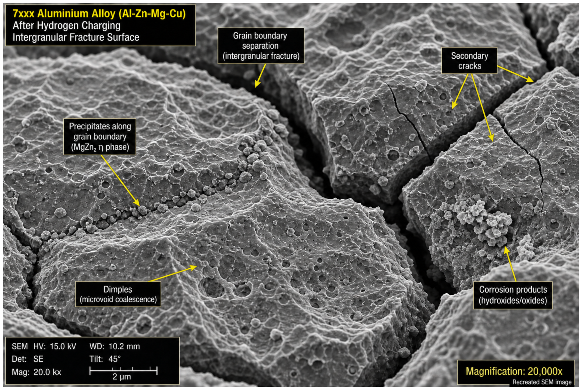
20. How does hydrogen embrittlement affect aluminium alloys?
Aluminium alloys, particularly the high-strength 2xxx (Al-Cu) and 7xxx (Al-Zn-Mg-Cu) series used in aerospace, are susceptible to hydrogen embrittlement, although the mechanisms differ from those in steel. The embrittlement in aluminium is closely linked to grain boundary chemistry, precipitate type, and whether hydrogen is introduced by corrosion or by high-temperature/high-pressure exposure.
Technical Detail and Definitions
- Aluminium has an FCC crystal structure, meaning hydrogen diffusion is relatively slow (similar to austenitic stainless steels).
- However, hydrogen interacts strongly with microstructural defects in aluminium, particularly:
- Grain boundary precipitates (e.g. MgZn₂ eta phase in 7xxx series).
- Vacancies, which are abundant in aluminium due to its relatively low vacancy formation energy.
- Interfaces between strengthening precipitates and the aluminium matrix.
High-strength aerospace aluminium alloys (7xxx series):
- Nature research published in 2022 demonstrated that hydrogen trapping at grain boundaries in 7xxx aluminium alloys promotes intergranular decohesion, the same basic HEDE mechanism as in steels.
- The co-segregation of alloying elements (Zn, Mg, Cu) and hydrogen at grain boundaries was shown to weaken cohesive strength.
- However, strong partitioning of hydrogen into second-phase precipitates within the grain interiors was found to remove solute hydrogen from the matrix, acting as beneficial traps (analogous to vanadium carbide trapping in steels).
- A 2022 Nature Communications study demonstrated that switching from eta-phase to T-phase precipitates reduced areal crack fractions by over 60%, demonstrating that microstructural engineering can dramatically reduce hydrogen embrittlement in aluminium.
2xxx series (Al-Cu) alloys:
- Alloy 2024-T3, widely used in aerospace structures, is susceptible to hydrogen-assisted intergranular corrosion and stress corrosion cracking.
- Hydrogen is typically introduced by aqueous corrosion or cathodic protection rather than by manufacturing processes like pickling.
Relevance to fastener applications:
- Aluminium alloy fasteners (e.g. 2024, 7075) used in aerospace are typically anodised or conversion-coated rather than electroplated, minimising manufacturing hydrogen risk.
- The primary concern is Environmental Hydrogen Embrittlement from long-term moisture exposure, corrosion, or cathodic coupling with dissimilar metals.
- Proper joint design to prevent crevice corrosion and galvanic coupling is the primary prevention strategy.
Source:
Nature - Hydrogen trapping and embrittlement in high-strength Al alloys
Nature Communications - Switching nanoprecipitates to resist hydrogen embrittlement
ScienceDirect - Hydrogen embrittlement of aluminium
21. How does hydrogen embrittlement affect nickel alloys?
Nickel and nickel-based superalloys have a complex relationship with hydrogen. Pure nickel and many nickel alloys are generally more resistant than high-strength steels due to their FCC crystal structure, but they are not immune. At high hydrogen pressures or in cathodically charged conditions, nickel alloys can suffer significant embrittlement, particularly the precipitation-hardened grades.
Technical Detail and Definitions
- Nickel has an FCC crystal structure, meaning hydrogen diffusion is slow compared to BCC iron.
- However, nickel has a relatively high hydrogen solubility, meaning it can absorb and retain significant quantities of hydrogen.
Nickel-based superalloys (Inconel, Waspaloy, Rene):
- Inconel 718, the most widely used nickel superalloy for pressure vessels and fasteners, is known to be susceptible to hydrogen embrittlement at high hydrogen pressures.
- NASA testing has documented measurable ductility loss in Inconel 718 under high-pressure gaseous hydrogen.
- However, in practice, nickel-hydrogen battery cells using Inconel 718 pressure vessels have not experienced embrittlement problems, suggesting that the in-service hydrogen pressures remain below the critical threshold.
- Precipitation-hardened nickel alloys (gamma-prime strengthened) can show increased susceptibility compared to solid-solution-strengthened grades.
K-Monel and Monel alloys:
- K-Monel (Monel K-500, a nickel-copper precipitation-hardened alloy) has been known to be embrittled by hydrogen at high pressure.
- Monel 400 (solid-solution nickel-copper) is generally resistant.
Relevance to fastener applications:
- Nickel alloy fasteners are primarily used in extreme environments: high temperature, high pressure, and aggressive chemical service.
- In oil and gas applications governed by NACE MR0175/ISO 15156, specific nickel alloy grades with controlled heat treatments are approved for sour (H2S) service where carbon steel fasteners would fail by sulphide stress cracking.
- Material testing under representative service conditions (temperature, pressure, hydrogen partial pressure) is essential for any high-strength nickel alloy fastener application.
Note: Trojan Special Fasteners does not work with Inconel, Hastelloy, or Monel alloys. This information is provided for reference purposes regarding joint assembly decisions.
Source:
NASA/TM-2016-218602 - Hydrogen Embrittlement
Science.gov - Hydrogen Embrittlement Susceptibility
ScienceDirect - Hydrogen Embrittlement overview
22. How does hydrogen embrittlement affect copper, brass, and bronze?
Copper, brass, and bronze alloys are generally considered immune to classical hydrogen embrittlement as it occurs in steels. However, oxygen-bearing copper (Electrolytic Tough Pitch copper, ETP, or C110) can suffer a specific and distinct form of hydrogen damage known as hydrogen disease or steam embrittlement.
Technical Detail and Definitions
Classical Hydrogen Embrittlement:
- Pure copper, brass (copper-zinc alloys), and bronze (copper-tin, copper-aluminium, and phosphor bronze alloys) do not suffer from the lattice-diffusion, stress-driven embrittlement mechanism that affects high-strength steels.
- This is because copper has an FCC crystal structure with very low hydrogen solubility and very slow hydrogen diffusion at ambient temperatures.
- There is no known risk of delayed brittle fracture from absorbed hydrogen in standard brass or bronze fasteners.
Hydrogen Disease in Oxygen-Bearing Copper (ETP/C110):
- Electrolytic Tough Pitch (ETP) copper contains approximately 200-400 ppm of oxygen, present as finely dispersed cuprous oxide (Cu₂O) particles throughout the microstructure.
- When ETP copper is exposed to hydrogen at elevated temperatures (above approximately 370 degrees Celsius), hydrogen diffuses through the copper and reacts with the Cu₂O inclusions:
- Cu₂O + H₂ -> 2Cu + H₂O (steam)
- The water vapour (steam) produced cannot escape from the solid metal and forms high-pressure bubbles at grain boundaries.
- These steam bubbles cause intergranular cracking and severe embrittlement.
- This mechanism is entirely different from hydrogen embrittlement of steels and only occurs at elevated temperatures during processes such as brazing, welding, or annealing in hydrogen-containing atmospheres.
Oxygen-Free Copper (OFC/C101):
- Oxygen-free high conductivity (OFHC) copper contains less than 10 ppm oxygen and is immune to hydrogen disease because there is no Cu₂O to react with.
- OFHC copper is specified for applications requiring hydrogen atmosphere brazing or service in reducing environments.
Brass:
- Standard brass alloys (CZ121, CZ108, etc.) do not contain dispersed Cu₂O particles and are therefore not susceptible to hydrogen disease.
- Brass is susceptible to stress corrosion cracking (season cracking) from ammonia and mercury, but this is a different mechanism from hydrogen embrittlement.
- Standard alpha brass fasteners do not require any hydrogen embrittlement precautions during electroplating or other manufacturing processes.
Bronze alloys (PB102, CA104, NES833):
- Phosphor bronze (PB102), aluminium bronze (CA104), and naval bronze (NES833) are not susceptible to hydrogen embrittlement.
- These alloys can be freely acid-pickled, electroplated, and processed without any risk of hydrogen-related failure.
- This makes bronze an excellent choice for fasteners in applications where hydrogen embrittlement of steel is a concern and corrosion resistance is required.
Source:
Wikipedia - Hydrogen Embrittlement (Copper section)
Eng-Tips Forum - Hydrogen embrittlement and brass
ASTM B577 - Detection of Cuprous Oxide in Copper
23. What is the susceptibility of spring steels?
Spring steels are among the most vulnerable materials to hydrogen embrittlement due to their extreme hardness levels (typically 45-60 HRC) and the enormous stored elastic energy they contain. A hydrogen embrittlement failure in a spring can result in sudden, violent shattering rather than a simple fracture.
Technical Detail and Definitions
- Common spring steels include:
- EN 10270-1 (carbon steel spring wire): patented, cold-drawn wire at 45-55 HRC.
- EN 10270-2 (oil-hardened and tempered spring wire): 45-52 HRC.
- AISI 6150 (chrome-vanadium spring steel): heat-treated to 44-50 HRC.
- AISI 9254 (silicon-manganese-chromium spring steel): 44-48 HRC.
Why spring steels are especially dangerous:
- The hardness range of 45-60 HRC places spring steels in the extreme susceptibility zone, with virtually zero tolerance for diffusible hydrogen.
- Springs are designed to operate at high sustained stress levels (typically 40-70% of tensile strength), providing the stress component required for hydrogen embrittlement.
- The high stored elastic energy means failure is sudden and violent: springs can fragment into multiple sharp pieces with considerable kinetic energy.
- The fine wire or thin section typical of springs provides a short hydrogen diffusion path, meaning hydrogen reaches critical concentrations faster than in larger-diameter bolts.
Manufacturing precautions:
- Acid pickling of spring steels must be avoided entirely. Mechanical cleaning (shot blasting, tumble finishing) is mandatory.
- If electroplating is absolutely required, baking must commence within 1 hour and continue for a minimum of 24 hours at 190-230 degrees Celsius.
- The preferred approach is to avoid electroplating entirely in favour of:
- Zinc flake coatings (Geomet, Magni, Delta Protekt).
- Mechanical galvanising.
- Organic coatings (powder coating, paint, PTFE).
- Phosphate and oil.
- Shot peening before coating is strongly recommended, as it introduces compressive residual stress at the surface, raising the effective threshold stress.
Source:
ISO/TR 20491:2019
BS ISO 9587:2007 - Pretreatment of iron or steel to reduce risk
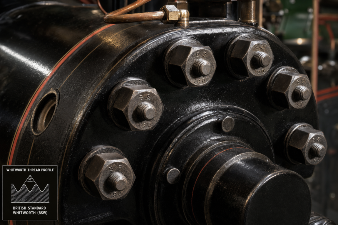
24. What is the hydrogen embrittlement risk for heritage fastener materials (BSW, BSF, BA)?
When reproducing obsolete British Standard Whitworth (BSW), British Standard Fine (BSF), or British Association (BA) thread fasteners using modern high-strength steels, a hydrogen embrittlement risk is introduced that did not exist in the original components. Original Victorian and Edwardian engineering used mild steel or wrought iron at hardness levels well below the susceptibility threshold.
Technical Detail and Definitions
- Original BSW, BSF, and BA fasteners were typically manufactured from:
- Mild steel (approximately 15-20 HRC, tensile strength 350-500 MPa).
- Wrought iron (even lower strength and hardness).
- Brass (completely immune to hydrogen embrittlement).
- At these low hardness levels, the original fasteners were effectively immune to hydrogen embrittlement, and the concept was not considered in their specification.
The problem with modern reproductions:
- Heritage railway, classic vehicle, and industrial preservation projects frequently require reproduction BSW and BSF fasteners.
- Modern reproduction may use high-tensile steels (Class 8.8 or 10.9 equivalent) to provide greater safety margins for operational heritage equipment.
- A reproduction stud manufactured in Class 10.9 material to a BSW thread form introduces a hydrogen embrittlement risk that the original designer never contemplated.
- Period-correct finishes (cadmium plating for post-1930s applications, black oxide, zinc electroplate) may introduce manufacturing hydrogen into materials that are now susceptible.
Steam locomotive applications:
- The restoration of Victorian and Edwardian steam locomotives involves the reproduction of studs, bolts, and nuts to original standards (such as the historic BS 190 for hexagon bolts and nuts).
- Cylinder head studs, motion assembly fasteners, and pressure vessel components may be specified in high-strength materials to meet modern boiler inspection requirements.
- Heritage railway boiler inspectors increasingly require evidence of hydrogen embrittlement awareness in fastener procurement specifications.
Best practice for heritage fastener manufacture:
- Specify the lowest property class that satisfies the structural requirements.
- Where Class 8.8 or below is adequate, hydrogen embrittlement risk is minimal and standard manufacturing processes are acceptable.
- Where Class 10.9 is required, ensure post-plating baking is performed to current standards (ISO 4042, ASTM F1941) even though no such requirement existed when the original equipment was built.
- Where possible, use non-electrolytic coatings that eliminate hydrogen risk whilst maintaining period-correct appearance (e.g. sherardising for a matt zinc finish, black oxide with oil for a dark appearance).
- Document all modern interventions in the restoration record to ensure future custodians understand which components incorporate modern hydrogen embrittlement prevention measures.
Trojan Special Fasteners manufactures precision BSW, BSF, BA, BSP, BSG, BSCy, and CEI thread fasteners by CNC bar turning in sizes from 2BA to 2 inches, supporting the heritage and restoration industries with modern manufacturing quality and full traceability.
Source:
BS 190:1924 - British Standard for black hexagon bolts and nuts
ISO 4042:2022 - Fasteners. Electroplated coating systems
25. What is the effect of small fastener diameter on hydrogen embrittlement risk?
Fasteners with a diameter below 6 mm are at significantly elevated risk of hydrogen embrittlement failure compared to larger sizes at the same property class. This is primarily due to the higher surface-to-volume ratio, shorter hydrogen diffusion distances, and proportionally sharper stress concentrations in the threads.
Technical Detail and Definitions
Surface-to-volume ratio:
- A smaller fastener has a larger surface area relative to its volume.
- Hydrogen absorption occurs at the surface. A higher surface-to-volume ratio means the fastener absorbs more hydrogen per unit mass during pickling or plating.
- For example, an M4 screw absorbs hydrogen approximately 3-4 times faster (per unit volume) than an M16 bolt during the same acid pickling treatment.
Diffusion distance:
- The maximum distance hydrogen must diffuse to reach the centre of the fastener cross-section is proportional to the diameter.
- In an M4 bolt, hydrogen reaches the central stress axis in a fraction of the time required for an M16 bolt.
- This means the critical concentration for crack initiation at the thread root is reached much faster in small fasteners.
Stress concentration:
- Thread geometry is proportionally sharper in small fasteners.
- The ratio of thread root radius to major diameter decreases as fastener size decreases.
- This creates higher peak stresses at the thread root relative to the nominal tensile stress in the bolt.
Process control challenges:
- Small fasteners are often batch-processed in bulk (barrel plating, batch pickling) alongside larger parts.
- Pickling time, acid concentration, and plating current density may be optimised for the larger parts in the batch, resulting in over-processing of the smaller ones.
- Individual tracking and quality verification is more difficult for very small fasteners.
Practical recommendations:
- Fasteners below M6 (or below #10 in imperial sizes) in Property Class 10.9 or above should receive the most stringent hydrogen embrittlement prevention measures.
- Baking should commence within 1 hour (not 4 hours) of plating for small, high-strength fasteners.
- Where possible, specify mechanical galvanising or zinc flake coatings to eliminate the hydrogen source entirely.
- Consider specifying A2 or A4 stainless steel alternatives for small-diameter applications where corrosion resistance is the primary requirement, eliminating the hydrogen risk altogether.
Trojan Special Fasteners manufactures precision CNC bar-turned nuts and special fasteners from M3 upwards in metric and from #8 upwards in Unified thread, with full traceability and material certification to ensure hydrogen embrittlement risk is managed across all size ranges.
Source:
ISO/TR 20491:2019
ISO 4042:2022 - Fasteners. Electroplated coating systems
BS ISO 9587:2007 - Pretreatment of iron or steel to reduce risk
[Shutterstock illustration: Size comparison photograph showing M3, M6, M12, and M24 hexagon bolts side by side, with an overlay diagram indicating relative surface-to-volume ratios and hydrogen diffusion distances for each size]
Section 3: Manufacturing Causes of Hydrogen Embrittlement
26. What is the effect of phosphorus and sulphur impurities on hydrogen embrittlement susceptibility?
The cleanliness of the steel, particularly the levels of phosphorus (P) and sulphur (S), has a profound effect on how much hydrogen a fastener can tolerate before failure. These tramp elements segregate to grain boundaries during steelmaking, acting as magnets for hydrogen atoms and dramatically reducing the critical hydrogen concentration required for crack initiation.
Technical Detail and Definitions
Phosphorus:
- Phosphorus segregates preferentially to prior austenite grain boundaries during austenitisation and tempering.
- At grain boundaries, phosphorus reduces the cohesive energy between adjacent grains, making them inherently weaker even without hydrogen.
- When hydrogen also segregates to the same grain boundaries, the combined weakening effect is synergistic, not merely additive.
- A steel with 0.025% phosphorus may have a threshold hydrogen concentration for failure that is 30-50% lower than a steel with 0.005% phosphorus at the same hardness.
- ISO 898-1 limits phosphorus to 0.025% maximum for Property Classes 10.9 and 12.9. Specialist fastener steels for critical applications may specify 0.010% maximum.
Sulphur:
- Sulphur forms manganese sulphide (MnS) inclusions that are elongated during hot rolling, creating stress-raising stringers within the microstructure.
- These inclusions act as hydrogen trap sites and as crack initiation points.
- MnS inclusions at or near grain boundaries provide sites where hydrogen can accumulate and initiate intergranular cracks.
- ISO 898-1 limits sulphur to 0.025% maximum for Property Classes 10.9 and 12.9.
The "sink effect":
- A dirty steel with high impurity levels effectively has more grain boundary "weak points" for hydrogen to exploit.
- This means dirty steels fail at much lower hydrogen concentrations than clean, vacuum-degassed steels at the same hardness.
- For ultra-critical applications (aerospace, nuclear), vacuum arc remelted (VAR) or electroslag remelted (ESR) steels with phosphorus below 0.005% and sulphur below 0.003% are specified.
Practical implications:
- When sourcing high-strength fastener steels, requesting mill certificates that confirm phosphorus and sulphur levels is a fundamental quality control step.
- Steel cleanliness is particularly important for Property Class 12.9 and above, where the margin between safe operation and failure is already extremely narrow.
- Free-machining steels (with deliberately elevated sulphur for machinability, e.g. 1215, 12L14) should never be used for high-strength, hydrogen-susceptible applications.
Source:
ScienceDirect - Effect of impurities on hydrogen embrittlement
BS EN ISO 898-1 - Mechanical properties of fasteners
27. How does the steel's microstructure affect hydrogen embrittlement susceptibility?
Microstructure is one of the most significant factors governing hydrogen embrittlement susceptibility. Tempered martensite is the most vulnerable common microstructure. Bainite offers improved resistance at equivalent strength levels. Austenite (FCC) is the most resistant. The quality of the tempered martensitic structure, particularly the tempering temperature and resulting carbide morphology, critically influences the threshold for hydrogen-induced failure.
Technical Detail and Definitions
Tempered Martensite (Most Susceptible):
- The standard microstructure for Property Classes 8.8, 10.9, and 12.9 fasteners per ISO 898-1.
- Martensite is formed by rapid quenching from the austenitising temperature, producing a highly strained body-centred tetragonal (BCT) lattice.
- Tempering relieves some internal stress and precipitates carbides, but the prior austenite grain boundary network remains as the primary weak path for hydrogen-assisted intergranular fracture.
- Under-tempering (insufficient time or temperature) leaves excessive internal strain and is a major risk factor.
- Over-tempering reduces strength below specification but improves hydrogen resistance.
Lower Bainite (Improved Resistance):
- Bainite is formed by isothermal transformation at temperatures between the pearlite and martensite formation ranges.
- Lower bainite (formed at lower transformation temperatures) has a finer microstructure with a more favourable carbide distribution than tempered martensite at equivalent hardness.
- Research has shown that bainitic steels can exhibit threshold hydrogen concentrations for failure that are 30-50% higher than tempered martensitic steels at the same strength level.
- Austempered fastener steels (bainitic) are being developed for applications where hydrogen embrittlement resistance is critical.
Pearlite and Ferrite (Resistant):
- The microstructure of low-carbon, low-strength steels (below approximately 25 HRC).
- The coarse, lamellar structure provides many benign hydrogen trap sites and has inherently high ductility.
- Hydrogen embrittlement is effectively impossible in fully pearlitic/ferritic steels at normal hydrogen concentrations.
Austenite (Most Resistant):
- The FCC microstructure of austenitic stainless steels and Hadfield manganese steels.
- Extremely slow hydrogen diffusion and high intrinsic ductility provide excellent resistance.
- As discussed in Question 18, resistance can be compromised by cold working (strain-induced martensite) or sensitisation.
Retained Austenite:
- Small amounts of retained austenite in otherwise martensitic steels can act as beneficial hydrogen traps.
- However, large amounts of retained austenite (from inadequate quenching) can transform to untempered martensite under stress, creating a locally brittle zone.
- Controlled amounts of retained austenite are being researched as a hydrogen mitigation strategy in advanced high-strength steels.
Source:
Oxford University - Hydrogen Embrittlement Research
Chemical Reviews - Hydrogen Embrittlement as a Conspicuous Material Challenge
Wikipedia - Hydrogen Embrittlement
28. How does duplex stainless steel perform regarding hydrogen embrittlement?
Duplex stainless steels, which contain approximately 50% austenite and 50% ferrite, exhibit intermediate susceptibility to hydrogen embrittlement. The ferritic phase (BCC) is susceptible, whilst the austenitic phase (FCC) is resistant. The overall performance depends on the phase balance, applied stress, and hydrogen charging conditions.
Technical Detail and Definitions
Common duplex grades include:
- 2205 (UNS S31803 / S32205): The most widely used duplex grade, with approximately 22% Cr, 5% Ni, 3% Mo.
- 2507 (UNS S32750): Super duplex, with approximately 25% Cr, 7% Ni, 4% Mo. Higher strength and corrosion resistance.
- 2304 (UNS S32304): Lean duplex, with approximately 23% Cr, 4% Ni.
Hydrogen behaviour in duplex microstructure:
- Hydrogen diffuses rapidly through the ferritic phase (BCC) but slowly through the austenitic phase (FCC).
- The ferrite provides the fast diffusion path for hydrogen to reach stress concentrations.
- The austenite acts as a barrier and a hydrogen trap, slowing the overall transport of hydrogen through the material.
- Cracks may initiate in the ferritic phase but are arrested or deflected at ferrite-austenite boundaries.
- This dual-phase "crack arrest" mechanism gives duplex steels better hydrogen resistance than fully ferritic steels at equivalent strength.
Risk factors:
- Phase imbalance: if the ferritic content exceeds approximately 60% (due to incorrect heat treatment or welding thermal cycles), the connected ferrite network provides an uninterrupted hydrogen diffusion path, dramatically increasing susceptibility.
- Cathodic overprotection in seawater service can charge duplex bolts with sufficient hydrogen to cause failure in the ferritic phase.
- Sigma phase precipitation (from prolonged exposure to 600-900 degrees Celsius) creates brittle intermetallic regions that concentrate hydrogen.
Practical guidance for duplex fasteners:
- Ensure proper solution annealing to achieve the correct 50/50 phase balance.
- Avoid cathodic overprotection: limit cathodic potential to minus 1050 mV (Ag/AgCl) in seawater to minimise hydrogen generation.
- Do not acid-pickle in reducing acids (HCl, H₂SO₄) without inhibitors. Oxidising acids (HNO₃/HF mixtures) are preferred for pickling duplex stainless steels.
- Duplex fasteners are a good compromise for marine and chemical applications where some hydrogen exposure is unavoidable but the extreme susceptibility of high-strength carbon steel must be avoided.
Source:
TWI Global - What is Hydrogen Embrittlement?
ScienceDirect - Hydrogen Embrittlement overview
29. How does hydrogen embrittlement affect titanium alloys?
Titanium alloys suffer from a distinct form of hydrogen damage involving the formation of brittle titanium hydrides (TiH₂) within the microstructure. This hydride formation mechanism is fundamentally different from the lattice decohesion and localised plasticity mechanisms that dominate in steels, but the practical result is equally catastrophic: sudden brittle fracture under sustained or cyclic loads.
Technical Detail and Definitions
- Titanium has a high solubility for hydrogen compared to iron, meaning it can absorb substantial quantities.
- At concentrations above approximately 150-200 ppm (depending on alloy and temperature), hydrogen precipitates as titanium hydride (TiH₂), a brittle ceramic phase.
- These hydride platelets form preferentially at grain boundaries, prior beta grain boundaries, and at alpha/beta phase interfaces.
- The hydrides act as crack initiation sites and as paths for crack propagation.
Alpha vs Beta phase susceptibility:
- Alpha-phase titanium (HCP structure): Low hydrogen solubility at room temperature. Excess hydrogen readily forms hydrides. Alpha alloys (e.g. Grade 1-4 commercially pure titanium) are susceptible at relatively low hydrogen levels.
- Beta-phase titanium (BCC structure): Much higher hydrogen solubility. Can absorb more hydrogen before hydrides form. However, once hydrides precipitate, beta alloys can fail catastrophically.
- Alpha-beta alloys (e.g. Ti-6Al-4V): The most common aerospace titanium alloy. Susceptibility depends on the alpha/beta phase ratio, grain structure, and hydrogen concentration. The maximum permissible hydrogen content is typically specified at 125-150 ppm.
Sources of hydrogen in titanium:
- Acid pickling in HF-based solutions (the standard pickling process for titanium) can introduce hydrogen if inadequately controlled.
- Cathodic charging in aqueous environments.
- High-temperature exposure to hydrogen-containing atmospheres during heat treatment.
- Galvanic coupling with less noble metals in seawater (titanium is cathodic and receives hydrogen from the galvanic reaction).
Mitigation:
- Control pickling time and acid concentration strictly per approved procedures.
- Vacuum anneal after any process suspected of introducing hydrogen (typically 650-750 degrees Celsius for 2-8 hours under vacuum).
- Specify maximum hydrogen content on material certificates (typically 125-150 ppm for Ti-6Al-4V).
- Avoid prolonged cathodic polarisation in aqueous service.
Note: Trojan Special Fasteners does not manufacture titanium fasteners. This information is provided for engineers specifying complete joint assemblies.
Source:
Wikipedia - Hydrogen Embrittlement (Titanium section)
NASA/TM-2016-218602 - Hydrogen Embrittlement
PMC - Hydrogen-Induced Degradation of Metallic Materials
30. Is there a universal hardness threshold below which hydrogen embrittlement cannot occur?
There is no single, absolute threshold. The commonly cited figure of 39 HRC (approximately 390 HV or 1200 MPa tensile strength) represents the level above which susceptibility is considered high and mandatory precautions (such as post-plating baking) are required by standards such as ISO 4042 and ASTM F1941. However, failures have been documented in the 32-39 HRC range, and some authorities recommend precautionary measures for any fastener above 34 HRC.
Technical Detail and Definitions
The relationship between hardness and susceptibility is a continuum, not a binary threshold:
- Below 30 HRC (approximately 300 HV, below 1000 MPa): Generally considered non-susceptible. Corresponds to Property Classes 4.6, 5.6, 5.8. Standard manufacturing processes require no special hydrogen embrittlement precautions.
- 30-34 HRC (approximately 300-340 HV, 1000-1100 MPa): Very low susceptibility. Corresponds to the lower end of Property Class 8.8. Precautions generally not required but may be specified for safety-critical applications.
- 34-39 HRC (approximately 340-390 HV, 1100-1200 MPa): Transitional zone. Corresponds to the upper end of Property Class 8.8 and the lower end of Property Class 10.9. Process control is important. Precautionary baking may be specified.
- 39-44 HRC (approximately 390-435 HV, 1200-1400 MPa): High susceptibility. Corresponds to Property Classes 10.9 (upper range) and 12.9. Mandatory baking per ISO 4042. Non-electrolytic coatings strongly preferred.
- Above 44 HRC (above 435 HV, above 1400 MPa): Extreme susceptibility. Corresponds to Property Class 14.9 and case-hardened surfaces. Electroplating typically prohibited. Maximum process control required.
Why there is no absolute threshold:
- Susceptibility depends on the interaction of hardness, hydrogen concentration, stress level, steel chemistry (P, S content), microstructure, and temperature.
- A "clean" vacuum-degassed steel at 40 HRC may be less susceptible than a "dirty" air-melted steel at 36 HRC with high phosphorus content.
- Residual stresses from manufacturing can push the effective stress above the threshold even at moderate hardness levels.
- Environmental hydrogen sources (corrosion, cathodic protection) can provide sustained hydrogen charging that eventually overwhelms even moderately resistant materials.
Industry practice:
- The safest approach is to apply hydrogen embrittlement precautions to all electroplated fasteners above Property Class 8.8 (including nut Grades 10 and 12).
- Many automotive OEM specifications now require baking for all electroplated fasteners above 320 HV (approximately 32 HRC).
- For non-electrolytic coatings (zinc flake, mechanical galvanising, sherardising), baking is not required at any hardness level because no manufacturing hydrogen is introduced.
Source:
ISO 4042:2022 - Fasteners. Electroplated coating systems
ASTM F1941 - Specification for Electrodeposited Coatings on Fasteners
Fastenal Technical Reference - Embrittlement
[Shutterstock illustration: Hardness versus susceptibility gradient chart showing HRC scale from 20 to 55, with colour-coded zones (green, amber, red) marking the non-susceptible, transitional, high-risk, and extreme-risk ranges, with Property Class labels overlaid]
31. How does acid pickling introduce hydrogen into fasteners?
Acid pickling is a chemical cleaning process used to remove mill scale, rust, and oxides from steel surfaces before coating. The chemical reaction between the acid and the iron in the steel releases vast quantities of atomic hydrogen at the metal surface, a significant proportion of which is absorbed into the steel lattice.
Technical Detail and Definitions
The chemical reaction:
- When hydrochloric acid (HCl) contacts iron:
- Fe + 2HCl -> FeCl₂ + 2H
- When sulphuric acid (H₂SO4) contacts iron:
- Fe + H₂SO₄ -> FeSO₄ + 2H
- In both cases, atomic hydrogen (H) is produced directly at the metal surface.
- Some of this hydrogen recombines into molecular hydrogen gas (H₂) and bubbles away harmlessly.
- However, a significant proportion of the atomic hydrogen is absorbed into the steel before it can recombine, because the steel surface presents a lower energy pathway than recombination.
Factors that increase hydrogen absorption during pickling:
- Acid concentration: Higher acid concentrations produce faster dissolution and more hydrogen.
- Temperature: Heated acid baths (common in production) accelerate the reaction and increase hydrogen uptake.
- Immersion time: Longer pickling times result in more hydrogen absorption.
- Surface condition: Heavily scaled surfaces require longer pickling, increasing exposure.
- Absence of inhibitors: Uninhibited acid baths attack the base metal aggressively, producing maximum hydrogen.
- Steel hardness: Higher-hardness steels absorb hydrogen more readily due to greater internal stress and dislocation density.
Inhibitors:
- Proprietary chemical additives are available that reduce the rate of acid attack on the base metal (iron) whilst still dissolving the oxides (mill scale, rust).
- Inhibitors work by adsorbing onto the clean metal surface, forming a protective barrier that reduces hydrogen evolution.
- However, inhibitors cannot completely eliminate hydrogen absorption; they reduce it, typically by 60-80%.
- Even with inhibitors, acid pickling of fasteners above 39 HRC introduces sufficient hydrogen to require post-pickling baking or post-plating baking.
The mechanical alternative:
- For fasteners above 1000 MPa tensile strength (approximately 32 HRC), mechanical cleaning is the authoritative alternative:
- Shot blasting with steel or glass media.
- Vibratory tumble finishing with ceramic or plastic media.
- Wire brushing or manual abrasive cleaning.
- Mechanical cleaning removes mill scale and oxides without any chemical reaction and therefore generates zero hydrogen.
- Additionally, shot blasting introduces beneficial compressive residual stress at the fastener surface, which actively resists hydrogen-assisted crack initiation.
Source:
BS ISO 9587:2007 - Pretreatment of iron or steel to reduce risk of hydrogen embrittlement
DST Chemicals - Knowledge on Hydrogen Embrittlement
32. How does electroplating cause hydrogen embrittlement?
Electroplating is the single most common cause of Internal Hydrogen Embrittlement in fasteners. During the electrolytic deposition of zinc, nickel, chromium, or cadmium, the fastener acts as the cathode in an electrical circuit. The cathodic reaction splits water molecules, generating atomic hydrogen directly at the fastener surface, where it is immediately absorbed into the steel lattice.
Technical Detail and Definitions
The cathodic reaction:
At the cathode (the fastener surface), two reactions occur simultaneously:
- Metal deposition: Zn₂+ + 2e- -> Zn (the desired coating)
- Hydrogen evolution: 2H+ + 2e- -> 2H -> H₂ (the unwanted side-reaction)
- The hydrogen evolution reaction produces atomic hydrogen (H) at the metal surface before it recombines into molecular hydrogen gas (H₂).
- During the brief interval between generation and recombination, atomic hydrogen is absorbed into the steel substrate.
Factors that increase hydrogen absorption during plating:
- Current density: Higher plating currents increase the rate of hydrogen evolution. Barrel plating is particularly problematic because current density varies across the barrel, with parts nearest the anode receiving excessive current.
- Bath chemistry: Acid zinc plating baths generate more hydrogen than alkaline zinc baths. Cyanide zinc baths produce the most hydrogen and create the least permeable zinc deposit, trapping hydrogen underneath.
- Plating time: Longer plating durations for thicker coatings result in greater total hydrogen absorption.
- Bath temperature: Higher temperatures increase both the plating rate and the hydrogen evolution rate.
- Bath contamination: Organic contaminants, metallic impurities (iron, copper, lead), and degraded bath additives reduce the efficiency of the plating reaction, diverting more current to hydrogen evolution.
- Coating type and thickness: Thicker coatings trap more hydrogen beneath the deposit. Bright, dense coatings (especially bright zinc and decorative chrome) are less permeable to hydrogen effusion during subsequent baking.
Why electroplated coatings trap hydrogen:
- The freshly deposited metal coating forms a relatively dense barrier on the steel surface.
- Hydrogen that has been absorbed into the steel must now diffuse through the coating to escape.
- Some coatings (chromium, nickel) are highly impermeable to hydrogen, making subsequent baking less effective.
- Other coatings (matte zinc, zinc-nickel) are more permeable, allowing more effective hydrogen removal during baking.
Source:
ISO 4042:2022 - Fasteners. Electroplated coating systems
ASTM F1941 - Specification for Electrodeposited Coatings on Fasteners
Advanced Plating Technologies - What is Hydrogen Embrittlement
33. Does the type of zinc plating process affect hydrogen risk?
Yes, significantly. The electrochemistry of the plating bath has a direct effect on the quantity of hydrogen generated and the permeability of the resulting zinc deposit. Alkaline non-cyanide zinc is generally preferred over acid zinc for high-strength fasteners due to lower hydrogen generation rates.
Technical Detail and Definitions
Acid Zinc Plating:
- Uses acidic electrolytes (zinc chloride or zinc sulphate based).
- Operates at lower pH, resulting in higher rates of hydrogen evolution at the cathode.
- Produces bright, smooth deposits with good visual appearance.
- The deposits tend to be denser and less permeable to hydrogen, making subsequent baking less efficient.
- Generally generates the most hydrogen of the common zinc plating processes.
Alkaline Non-Cyanide Zinc Plating:
- Uses alkaline electrolytes (sodium or potassium hydroxide based with zinc oxide).
- Operates at high pH, resulting in lower hydrogen evolution rates compared to acid zinc.
- Produces matte or semi-bright deposits that are more porous and permeable to hydrogen.
- The greater permeability improves the effectiveness of post-plating baking.
- Generally the preferred process for high-strength fasteners.
Cyanide Zinc Plating (Legacy Process):
- Uses sodium or potassium cyanide as the complexing agent.
- Historically common but now largely replaced due to environmental and health regulations.
- Generates substantial hydrogen.
- The cyanide-based deposits are extremely dense and impermeable, making hydrogen removal by baking very difficult.
- The presence of cyanide "poisons" the hydrogen recombination reaction, increasing the proportion of atomic hydrogen that enters the steel rather than evolving as gas.
- Cyanide zinc is the most hazardous process for hydrogen embrittlement and should be avoided entirely for susceptible fasteners.
Zinc-Alloy Plating (Zinc-Nickel, Zinc-Iron, Zinc-Cobalt):
- Zinc-nickel alloy plating (typically 12-16% Ni) is increasingly specified for automotive and aerospace fasteners due to superior corrosion performance.
- Hydrogen generation rates are similar to or slightly higher than equivalent non-alloy zinc processes.
- Post-plating baking requirements are the same as for standard zinc electroplate.
- The alloy deposit is generally more permeable than pure bright zinc, improving baking effectiveness.
Source:
ISO 4042:2022 - Fasteners. Electroplated coating systems
ASTM B633 - Electrodeposited Coatings of Zinc on Iron and Steel
34. How does phosphating contribute to hydrogen embrittlement?
Phosphating (also called phosphate conversion coating) is a chemical treatment applied to steel surfaces to improve paint adhesion, provide temporary corrosion protection, and reduce friction during assembly. The chemical reaction between the phosphating solution and the steel surface generates a small amount of atomic hydrogen, making phosphating a secondary but non-trivial source of manufacturing hydrogen in high-strength fasteners.
Technical Detail and Definitions
The phosphating reaction:
- Phosphating solutions contain dilute phosphoric acid with metal phosphate salts (zinc, manganese, or iron phosphate).
- The acid component dissolves a microscopic layer of the steel surface, releasing atomic hydrogen in the process.
- The dissolved iron reacts with the phosphate ions to form an insoluble crystalline iron/zinc/manganese phosphate layer on the surface.
- The hydrogen generated is less than during full acid pickling but is not zero.
Types of phosphate coating and relative risk:
- Zinc Phosphate: The most common type for fasteners. Moderate hydrogen generation. Crystal size and coating weight are controlled by accelerators and bath chemistry.
- Manganese Phosphate: Used primarily for bearing surfaces and firearms. Generally thicker coatings with slightly higher hydrogen generation due to more aggressive bath chemistry.
- Iron Phosphate: A lighter, thinner coating used primarily as a paint pretreatment. Lower hydrogen generation than zinc or manganese phosphate.
Risk assessment:
- For fasteners below 34 HRC (Property Classes 8.8 and below), phosphating presents negligible hydrogen embrittlement risk.
- For fasteners at 34-39 HRC (upper Class 8.8 and Class 10.9), the hydrogen from phosphating is generally insufficient to cause failure on its own, but it adds to any hydrogen from prior processing steps (pickling, descaling).
- For fasteners above 39 HRC (Class 12.9 and case-hardened parts), the cumulative hydrogen from phosphating should be considered, and post-phosphating baking may be specified for critical applications.
Mitigation:
- Minimise phosphating immersion time to the minimum required for adequate coating formation.
- Use accelerated phosphating processes that reduce immersion time.
- Ensure thorough rinsing after phosphating to remove residual acid.
- For susceptible fasteners, specify mechanical cleaning (shot blast) before phosphating to avoid the cumulative hydrogen load of pickling followed by phosphating.
Source:
BS ISO 9587:2007 - Pretreatment of iron or steel to reduce risk
Wikipedia - Hydrogen Embrittlement (Manufacturing section)
[Shutterstock illustration: Flowchart showing the fastener coating process sequence: raw bar stock, machining, heat treatment, surface preparation (showing the fork between acid pickling and mechanical cleaning), phosphating/plating, baking, chromate conversion, inspection, with hydrogen risk indicators at each stage]
35. How does welding introduce hydrogen into fasteners and assemblies?
Welding is a major source of hydrogen in steel structures and can indirectly affect fasteners in welded assemblies. Hydrogen is introduced from moisture in electrode coatings, shielding gases, fluxes, or from the base metal surface. The resulting hydrogen-induced cracking (commonly called "cold cracking" or "delayed cracking") is one of the most common and dangerous welding defects.
Technical Detail and Definitions
Sources of hydrogen during welding:
- Electrode moisture: Cellulosic and basic electrode coatings absorb atmospheric moisture. When heated in the arc, this moisture decomposes into atomic hydrogen and oxygen. This is the single most common cause of weld hydrogen problems.
- Shielding gas contamination: Moisture or hydrocarbon contamination in argon, CO₂, or mixed shielding gases introduces hydrogen into the weld pool.
- Flux moisture: Submerged arc welding fluxes and flux-cored wire fills absorb moisture from the atmosphere.
- Surface contaminants: Oil, grease, paint, rust, and moisture on the base metal or filler wire decompose in the arc, releasing hydrogen.
- Base metal hydrogen: The base metal itself may contain residual hydrogen from steelmaking or prior processing.
How welding hydrogen affects fasteners:
- Fasteners threaded into welded structures may be affected if the heat-affected zone (HAZ) of the weld extends to the threaded hole.
- Studs welded directly to structural members (e.g. Nelson studs, weld studs) are exposed to the full weld hydrogen load.
- Hydrogen from the weld can diffuse through the HAZ and into adjacent bolted connections over time.
- Fasteners installed into structures that have not been properly post-weld heat treated may be subjected to elevated residual stresses from weld shrinkage, increasing the driving force for hydrogen migration.
Prevention:
- Use low-hydrogen welding electrodes (e.g. AWS E7018, E8018, E9018) and ensure proper drying before use (typically 350-400 degrees Celsius for 1-2 hours per the electrode manufacturer's instructions).
- Preheat the base metal to slow the cooling rate and allow hydrogen to diffuse out before the weld cools below the martensite start temperature.
- Apply post-weld heat treatment (PWHT) to allow hydrogen diffusion and stress relief.
- Maintain dry storage conditions for all welding consumables.
- Specify maximum diffusible hydrogen levels in welding procedure specifications (e.g. H5 or H10 per ISO 3690, indicating maximum 5 or 10 ml of hydrogen per 100 g of deposited weld metal).
Source:
TWI Global - What is Hydrogen Embrittlement?
Wikipedia - Hydrogen Embrittlement (Welding section)
36. Can heat treatment atmospheres introduce hydrogen?
Yes. Heat treatment furnace atmospheres can be a significant source of hydrogen if not properly controlled. Endothermic gas atmospheres, dissociated ammonia, and even residual moisture in "inert" atmospheres can introduce hydrogen into the steel during austenitising, carburising, or annealing operations.
Technical Detail and Definitions
Endothermic gas atmospheres:
- Endothermic gas is widely used as a carrier gas in heat treatment furnaces. Its typical composition is approximately 40% H₂, 20% CO, and 40% N₂.
- At austenitising temperatures (800-900 degrees Celsius for fastener steels), the steel readily absorbs hydrogen from the atmosphere.
- The majority of this hydrogen should be released during subsequent quenching and tempering, but residual hydrogen can remain, particularly in thick sections or very hard materials.
Carburising atmospheres:
- Carburising introduces carbon into the surface of low-carbon steels using carbon-rich atmospheres (endothermic gas enriched with methane or propane).
- These atmospheres contain substantial hydrogen.
- The high temperatures involved promote hydrogen absorption.
- The resulting case-hardened surface (often 55-62 HRC) is extremely susceptible to any retained hydrogen.
Dissociated ammonia:
- Used in nitriding and some annealing operations.
- Dissociated ammonia produces a 75% H₂ / 25% N₂ atmosphere.
- This high hydrogen content is a significant source of absorption.
Vacuum and inert gas atmospheres:
- Vacuum heat treatment minimises hydrogen exposure because the low pressure removes gases from the steel surface rather than introducing them.
- However, vacuum furnaces with inadequate leak integrity may introduce moisture, which decomposes into hydrogen at high temperature.
- Argon and nitrogen atmospheres should be dried (dew point below minus 40 degrees Celsius) to prevent moisture-related hydrogen pickup.
Mitigation:
- For susceptible fastener grades, vacuum or controlled-atmosphere heat treatment with verified low dew point is preferred.
- Monitor furnace atmosphere composition and dew point regularly.
- Ensure rapid quenching after austenitising to "freeze" hydrogen in solution, followed by adequate tempering at the correct temperature to allow controlled hydrogen release.
- If hydrogen levels are a concern after heat treatment, a dedicated de-gassing treatment (baking at 190-230 degrees Celsius for 4-8 hours) can be applied before subsequent processing.
Source:
BS ISO 9587:2007 - Pretreatment of iron or steel to reduce risk
Inspectioneering - What is Hydrogen Embrittlement
37. Can machining lubricants and cutting fluids introduce hydrogen?
Yes. Certain machining lubricants and cutting fluids can decompose at the tool-workpiece interface, releasing hydrogen that is absorbed into the freshly cut metal surface. This is a secondary but recognised source of hydrogen, particularly significant when machining high-strength, heat-treated materials.
Technical Detail and Definitions
How cutting fluids introduce hydrogen:*
- At the cutting zone, temperatures can reach 300-800 degrees Celsius depending on the material, tool geometry, and cutting parameters.
- Water-based coolants decompose into hydrogen and oxygen at the freshly machined surface.
- Oil-based and semi-synthetic fluids containing sulphur, chlorine, or phosphorus extreme-pressure (EP) additives decompose at elevated temperatures, releasing hydrogen and other reactive species.
- Sulphur-containing EP additives are particularly problematic because sulphur poisons the hydrogen recombination reaction (the same mechanism as H₂S in sour gas service), dramatically increasing the proportion of atomic hydrogen absorbed into the steel.
Risk assessment:
- For fasteners below 34 HRC, hydrogen from machining lubricants is generally insignificant.
- For fasteners above 39 HRC (particularly if machined after heat treatment, which is atypical but sometimes necessary), the risk is meaningful.
- The risk is highest during grinding operations, where the combination of high surface temperatures, large surface areas, and water-based coolant creates ideal conditions for hydrogen absorption.
Mitigation:
- Prefer dry machining or minimum quantity lubrication (MQL) for post-heat-treatment machining of susceptible materials.
- Avoid sulphur-containing EP additives on materials above 39 HRC.
- Use chlorinated paraffin-based or synthetic ester-based cutting fluids that do not produce hydrogen-promoting decomposition products.
- If water-based coolants must be used on susceptible materials, consider a post-machining baking step (190-230 degrees Celsius for 4 hours) as a precautionary measure.
- Complete all machining operations before final heat treatment wherever the component design permits, so that any machining-introduced hydrogen is released during the austenitising and tempering cycle.
Source:
ISO/TR 20491:2019
Oxford University - Hydrogen Embrittlement Research
38. Does hot-dip galvanising cause hydrogen embrittlement?
The molten zinc immersion step of hot-dip galvanising does not directly introduce hydrogen, because no electrochemical reaction occurs. However, the acid pickling pre-treatment required before galvanising is a major source of hydrogen, and the thermal cycle of the galvanising bath can release trapped residual hydrogen, potentially causing failure if the pre-treatment was not properly controlled.
Technical Detail and Definitions
The hot-dip galvanising process sequence:
- Degreasing (caustic alkali wash).
- Acid pickling (hydrochloric or sulphuric acid to remove mill scale and rust). This step generates hydrogen.
- Rinsing.
- Fluxing (zinc ammonium chloride solution). This step can generate a small amount of hydrogen.
- Immersion in molten zinc at approximately 450 degrees Celsius.
- Cooling and inspection.
The hydrogen risk:
- The acid pickling step is the primary source of hydrogen (see Question 31).
- The molten zinc bath temperature (450 degrees Celsius) is well above the baking temperature used for hydrogen relief (190-230 degrees Celsius). This thermal excursion has two competing effects:
- Beneficial: It accelerates hydrogen diffusion, allowing some absorbed hydrogen to escape through the surface before the zinc coating solidifies.
- Detrimental: It can release previously trapped hydrogen from deep within the section, mobilising it to grain boundaries and stress concentrations.
- If the pickling step introduced excessive hydrogen and the fastener was not mechanically cleaned beforehand, the galvanising thermal cycle may cause failure during or immediately after the process.
Risk thresholds:
- Fasteners below approximately 34 HRC (below 1100 MPa tensile strength) are generally safe for hot-dip galvanising with standard acid pickling pre-treatment.
- Fasteners at 34-39 HRC (Property Class 10.9) require careful control of pickling time and acid concentration, or preferably mechanical cleaning (shot blasting) before galvanising.
- Fasteners above 39 HRC (Property Class 12.9 and above) should not normally be hot-dip galvanised due to the combination of pickling hydrogen risk and the uncontrolled thermal cycle.
ISO 10684 requirements:
- ISO 10684 (Hot-dip galvanised coatings on fasteners) specifies requirements for galvanised fasteners and includes precautions for high-strength grades.
- For Property Class 10.9, mechanical cleaning before galvanising is recommended.
- For Property Class 12.9, the standard advises against hot-dip galvanising.
Source:
ISO 1461 - Hot dip galvanized coatings on iron and steel
ISO 10684 - Hot-dip galvanized coatings on fasteners
39. Does sherardising introduce hydrogen?
No. Sherardising is a thermal diffusion zinc coating process that does not involve any electrochemical reaction or acid immersion, making it inherently free from hydrogen embrittlement risk. Sherardising is one of the safest coating options for high-strength susceptible fasteners.
Technical Detail and Definitions
The sherardising process:
- Fasteners are tumbled in a sealed, rotating drum with zinc dust at approximately 300-400 degrees Celsius for 1-6 hours (depending on the required coating thickness).
- At these temperatures, zinc atoms diffuse into the steel surface, forming a series of zinc-iron intermetallic layers (gamma, delta, and zeta phases).
- No acid pickling pre-treatment is required. Parts are typically cleaned by shot blasting before sherardising.
- No electricity or electrolyte is used. There is no cathodic reaction and therefore no hydrogen generation.
Advantages for susceptible fasteners:
- Zero hydrogen embrittlement risk.
- Uniform coating thickness, even in recessed areas, threads, and complex geometries.
- Good corrosion resistance (comparable to electroplated zinc at equivalent thickness).
- The matte grey appearance is period-appropriate for heritage and restoration applications.
- The process temperature (300-400 degrees Celsius) is above the baking temperature, providing an incidental hydrogen de-gassing benefit if any residual hydrogen from prior operations exists.
- Post-sherardising passivation with trivalent chromate can be applied without hydrogen risk.
Limitations:
- Limited coating thickness range (typically 15-45 micrometres).
- The matte appearance may not be acceptable where bright, decorative finishes are required.
- Higher per-piece cost than barrel zinc electroplating for high-volume production.
- Not all sherardising contractors can handle very large or very small fasteners.
Source:
BS EN 13811 - Sherardizing. Zinc diffusion coatings on iron and steel
BS 7371-1:2009 - Coatings on metal fasteners. Selection guidelines
[Shutterstock illustration: Comparison photograph showing three identical hexagon bolts side by side: one bright zinc electroplated, one sherardised (matte grey), and one zinc flake coated, with labels identifying each coating type and its hydrogen embrittlement risk level]
40. Does black oxide finishing cause hydrogen embrittlement?
Black oxide is a chemical conversion coating formed by immersing steel parts in a hot alkaline bath (typically sodium hydroxide with sodium nitrite and other oxidising agents at 140-150 degrees Celsius). The process generates a small amount of atomic hydrogen, but significantly less than acid pickling or electroplating. The risk is low for most fastener grades but not zero for the highest strength levels.
Technical Detail and Definitions
The black oxide reaction:
- The hot alkaline nitrite bath converts the steel surface to magnetite (Fe3O4), a thin, adherent black iron oxide layer approximately 1-3 micrometres thick.
- The reaction involves a mild dissolution of the steel surface, producing a small amount of atomic hydrogen.
- The quantity of hydrogen generated is substantially less than acid pickling or electroplating because the bath is alkaline (high pH), not acidic.
Risk assessment by property class:
- Property Classes 4.6 to 8.8: No hydrogen embrittlement risk from black oxide. No precautions required.
- Property Class 10.9: Very low risk. Standard practice does not require post-treatment baking, but some safety-critical specifications may require it as a precaution.
- Property Class 12.9: Low but non-zero risk. Precautionary baking (190-230 degrees Celsius for 4-8 hours) after black oxide treatment is recommended for safety-critical applications.
- Case-hardened parts (above 45 HRC): Post-treatment baking should be considered for all case-hardened parts receiving black oxide.
Additional considerations:
- Black oxide provides minimal corrosion protection on its own. It is typically applied with a supplementary oil, wax, or lacquer to provide temporary rust prevention.
- The alkaline pre-cleaning and rinsing steps in the black oxide process are generally benign from a hydrogen perspective.
- If the black oxide process includes an acid dip or acid activation step (as some proprietary processes do), the hydrogen risk from that acid step must be assessed separately.
Source:
ISO 11408 - Chemical conversion coatings. Black oxide coatings on iron and steel
BS ISO 9587:2007 - Pretreatment of iron or steel to reduce risk
41. How do mechanical coatings eliminate hydrogen risk?
Mechanical coatings (also called peen plating or mechanical galvanising) apply metal coatings without any electrochemical reaction, acid immersion, or high-temperature process. Metal particles (typically zinc or zinc-tin) are physically hammered onto the fastener surface using glass bead impact media in a tumbling barrel. Because no hydrogen-generating chemistry is involved, the process is inherently free from hydrogen embrittlement risk.
Technical Detail and Definitions
The mechanical plating process:
- Fasteners are loaded into a rotating barrel with water, proprietary chemical promoters, glass bead impact media, and zinc dust or zinc-tin powder.
- The tumbling action causes the glass beads to cold-weld the metal particles onto the fastener surface through repeated impact.
- Coating thickness is controlled by the quantity of metal powder and the tumbling time.
- Typical coating thickness range is 5-75 micrometres.
- The process operates at ambient temperature.
Why mechanical coating eliminates hydrogen risk:
- No electrolytic reaction occurs. There is no cathodic hydrogen evolution.
- No acid pickling is required. Parts are typically cleaned by alkaline degreasing and glass bead peening within the same barrel.
- No high-temperature exposure occurs. No hydrogen is mobilised from prior processing.
- The resulting coating is slightly porous, which actually benefits any residual hydrogen escape from prior operations.
Standards:
- ASTM B695 covers the standard specification for coatings of zinc mechanically deposited on iron and steel.
- ASTM B696 covers coatings of cadmium mechanically deposited.
- ISO 12683 covers mechanically deposited coatings of zinc.
Limitations:
- The coating has a matte, slightly rough appearance, not suitable where bright decorative finishes are required.
- Thread dimensional control requires careful process management to avoid excessive build-up.
- Not all fastener geometries are suitable for barrel tumbling (e.g. very long, slender parts may tangle).
- Per-piece costs are typically higher than barrel zinc electroplating for high-volume applications.
Source:
ASTM B695 - Coatings of Zinc Mechanically Deposited on Iron and Steel
BS 7371-1:2009 - Coatings on metal fasteners
- 42. What is the hydrogen embrittlement risk from cadmium plating?
Cadmium electroplating generates hydrogen by the same cathodic mechanism as zinc electroplating (see Question 32) and therefore carries the same Internal Hydrogen Embrittlement risk. However, cadmium has the advantage of being relatively permeable to hydrogen, making post-plating baking more effective. Environmental regulations increasingly restrict cadmium use due to its extreme toxicity.
Technical Detail and Definitions
Why cadmium was historically preferred:
- Cadmium provides exceptional corrosion protection, particularly in marine and aerospace environments.
- The cadmium deposit is more hydrogen-permeable than zinc, allowing more efficient hydrogen removal during baking.
- Cadmium has superior lubricity (lower friction coefficient) compared to zinc, important for torque-tension accuracy in bolted joints.
- Cadmium maintains corrosion protection at high temperatures (up to approximately 230 degrees Celsius), whereas zinc becomes less effective.
Current regulatory status:
- Cadmium is classified as a Category 1B carcinogen under EU REACH regulation.
- Use is prohibited in consumer products within the EU under the RoHS Directive and REACH Annex XVII.
- Exemptions exist for certain aerospace, defence, and safety-critical industrial applications where no technically equivalent alternative exists.
- The global trend is toward elimination of cadmium in all applications.
Cadmium replacement coatings:
- Zinc-nickel alloy electroplate (12-16% Ni) is the most common cadmium replacement for aerospace and defence applications.
- Zinc-nickel provides comparable corrosion resistance and good hydrogen permeability for baking.
- Zinc flake coatings (non-electrolytic) are increasingly specified as cadmium replacements where the elimination of all electrochemical hydrogen risk is preferred.
- IVD (Ion Vapour Deposited) aluminium is used as a cadmium replacement in some aerospace applications.
Heritage and restoration note:
- Many heritage and vintage vehicles, aircraft, and equipment originally specified cadmium-plated fasteners.
- Modern restoration must balance authenticity with regulatory compliance and safety.
- Zinc-nickel electroplate with appropriate passivation provides the closest visual and functional match to cadmium whilst complying with current regulations.
- Post-plating baking must be applied regardless of the replacement coating chosen.
Source:
ASTM F1941 - Specification for Electrodeposited Coatings on Fasteners
BS 7371-1:2009 - Coatings on metal fasteners
43. How does chromium plating affect hydrogen embrittlement?
Hard chromium and decorative chromium plating present a particularly severe hydrogen embrittlement risk because the chromium deposit is highly impermeable to hydrogen. This means that hydrogen absorbed during the plating process (or from prior operations) is effectively sealed in beneath the chromium layer, making post-plating baking far less effective than with more permeable coatings like zinc.
Technical Detail and Definitions
The chromium plating process:
- Chrome plating uses a chromic acid (CrO3) electrolyte at high current densities.
- The process has very low cathode efficiency (typically 10-25%), meaning that 75-90% of the electrical energy is consumed by hydrogen evolution rather than chromium deposition.
- This results in enormous quantities of atomic hydrogen being generated at the fastener surface.
- Simultaneously, the deposited chromium forms an extremely dense, non-porous coating that acts as a barrier to hydrogen escape.
Why chrome plating is the highest-risk electroplating process:
- Maximum hydrogen generation (low cathode efficiency).
- Maximum hydrogen retention (impermeable coating barrier).
- The combination means that even aggressive baking may not remove sufficient hydrogen to prevent embrittlement.
- Micro-cracking in hard chrome deposits can act as local stress raisers, providing additional crack initiation sites.
Practical guidance:
- Hard chromium plating of fasteners above 34 HRC should be avoided wherever possible.
- For decorative applications, specifying nickel-chrome over a copper undercoat may slightly improve hydrogen removal through the copper layer's moderate permeability.
- If chrome plating is absolutely essential on susceptible parts, consider applying a thin initial chrome layer, baking, and then completing the plating to final thickness ("interrupted plating and baking").
- Extended baking times (24-48 hours) are typically required due to the low hydrogen permeability of chromium.
- Non-electrolytic alternatives include:
- Hard anodising (for aluminium substrates).
- PVD (Physical Vapour Deposition) chrome-look coatings.
- HVOF (High Velocity Oxy-Fuel) or thermal spray chrome carbide coatings.
Source:
ISO 4042:2022 - Fasteners. Electroplated coating systems
Advanced Plating Technologies - What is Hydrogen Embrittlement
44. How does nickel plating affect hydrogen embrittlement?
Nickel electroplating generates hydrogen at the cathode in the same manner as other electrolytic processes. Additionally, like chromium, electrolytic nickel deposits are relatively dense and impermeable, hindering hydrogen effusion during subsequent baking. Electroless (autocatalytic) nickel plating introduces less hydrogen than electrolytic nickel but is not hydrogen-free and still requires baking for susceptible materials.
Technical Detail and Definitions
Electrolytic Nickel Plating:
- Uses nickel sulphate/nickel chloride electrolytes (Watts bath or sulphamate bath).
- Cathode efficiency is moderate (90-97%), so less hydrogen is evolved per unit thickness than in chrome plating.
- However, the nickel deposit is dense and relatively impermeable to hydrogen.
- Baking requirements are similar to zinc electroplate: 190-230 degrees Celsius for 8-24 hours, commencing within 4 hours.
- Bright nickel deposits (containing sulphur-based brighteners) are more impermeable than matte nickel, making baking less effective.
Electroless Nickel Plating:
- An autocatalytic (chemical reduction) process that does not use external electrical current.
- Uses sodium hypophosphite as the reducing agent in most formulations.
- The reduction reaction produces some hydrogen at the workpiece surface, but at a lower rate than electrolytic processes.
- The resulting nickel-phosphorus alloy deposit (typically 8-12% P) has moderate hydrogen permeability.
- Baking is still required for fasteners above 39 HRC, but the lower hydrogen load typically results in better outcomes.
- Electroless nickel baking may be combined with the precipitation hardening heat treatment (approximately 300-400 degrees Celsius) that is often applied to improve the hardness and wear resistance of the EN deposit.
Source:
ASTM B733 - Electroless Nickel Plating
ISO 4042:2022
[Shutterstock illustration: Comparison table showing five common electroplated coating types (zinc, zinc-nickel, cadmium, nickel, chrome) ranked by hydrogen generation rate, coating permeability, and baking effectiveness, with colour-coded risk ratings]
45. Does tin plating cause hydrogen embrittlement?
Tin electroplating generates hydrogen via the cathodic reaction in the same way as other electrolytic processes. The quantity of hydrogen generated varies with the type of tin plating bath. An additional complication is that standard baking temperatures (190-230 degrees Celsius) can adversely affect the properties of tin deposits, requiring lower baking temperatures and correspondingly longer durations.
Technical Detail and Definitions
Tin plating baths and hydrogen generation:
- Acid tin (stannous sulphate): Moderate hydrogen generation, comparable to acid zinc. Commonly used for electronic and solderability applications.
- Alkaline tin (stannate): Generally lower hydrogen generation than acid tin. Produces a matte deposit.
- Bright tin: Contains organic brightening agents that can increase hydrogen co-deposition.
Baking complications:
- Standard post-plating baking temperatures (190-230 degrees Celsius) can cause:
- Tin oxidation and discolouration.
- Intermetallic compound (Cu6Sn5, Cu3Sn) growth at copper/tin interfaces, affecting solderability.
- Tin whisker promotion in some circumstances.
- To avoid these effects, tin-plated susceptible fasteners are typically baked at lower temperatures:
- 150-175 degrees Celsius for 8-24 hours, or
- 130-150 degrees Celsius for 24-48 hours.
- The lower temperature requires proportionally longer duration to achieve equivalent hydrogen removal.
Practical guidance:
- Tin-plated fasteners above 39 HRC require careful specification of baking parameters that balance hydrogen removal against tin deposit quality.
- For food-contact or electronic applications where tin plating is specified for functional reasons, consider whether the application truly requires high-strength steel, or whether a lower-strength (non-susceptible) grade would be adequate.
Source:
ASTM B545 - Electrodeposited Coatings of Tin
ASTM B850 - Guide for Post-Coating Treatments of Steel
46. How does cold forming (heading and rolling) affect hydrogen embrittlement risk?
Cold forming operations such as cold heading, cold forging, thread rolling, and knurling introduce significant cold work into the fastener material, increasing the dislocation density and creating residual stress patterns. These effects can increase hydrogen embrittlement susceptibility by creating more reversible trap sites and higher internal stresses that drive hydrogen migration.
Technical Detail and Definitions
Effects of cold work on susceptibility:
- Cold deformation increases the dislocation density by orders of magnitude. Each dislocation acts as a reversible hydrogen trap site.
- The high density of reversible traps temporarily "soaks up" hydrogen, but releases it under sustained stress or elevated temperature, feeding hydrogen to grain boundaries and crack initiation sites.
- Cold work introduces residual stresses. Tensile residual stresses on the surface accelerate hydrogen migration inward.
- In austenitic stainless steels, severe cold work can create strain-induced martensite, converting a resistant FCC material into a locally susceptible BCC structure.
Thread rolling timing (critical consideration):
- Thread rolling before heat treatment:
- The cold work from rolling is largely relieved during subsequent austenitising and quenching.
- Residual stresses are reset by the heat treatment cycle.
- The result is a thread with low residual stress after tempering.
- This is the preferred sequence for hydrogen-susceptible materials.
- Thread rolling after heat treatment:
- Used to maximise fatigue life (rolling introduces compressive residual stress at the thread root).
- However, the subsurface compensating tensile stress remains permanently in the hardened material.
- The high dislocation density in the rolled zone creates a dense network of reversible hydrogen traps.
- If the fastener is subsequently acid-pickled or electroplated, the rolled threads absorb hydrogen rapidly and concentrate it in the high-stress region.
- Post-rolling baking is essential if the part will be exposed to hydrogen sources.
Practical guidance:
- For susceptible property classes (10.9, 12.9), specify thread rolling before heat treatment unless fatigue life is the overriding design consideration.
- If thread rolling after heat treatment is required, ensure that all subsequent coating operations are non-electrolytic (zinc flake, mechanical galvanising) to avoid introducing hydrogen into the highly stressed rolled zone.
- If electroplating of post-rolled threads is unavoidable, commence baking within 1 hour (not 4 hours) due to the accelerated hydrogen uptake in the cold-worked region.
Source:
Oxford University - Hydrogen Embrittlement Research
ISO/TR 20491:2019
47. Does grinding introduce hydrogen into fasteners?
Yes. Grinding operations can introduce hydrogen through two simultaneous mechanisms: thermal decomposition of water-based grinding coolant at the grinding interface, and the extreme localised heating that can cause microstructural changes in the surface layer, creating a zone of elevated susceptibility.
Technical Detail and Definitions
Hydrogen sources during grinding:
- Water-based coolant is decomposed at the grinding zone, where localised temperatures can exceed 500-1000 degrees Celsius despite the bulk coolant temperature remaining low.
- The freshly ground surface is chemically reactive and absorbs atomic hydrogen readily.
- Oil-based coolants can also decompose, releasing hydrogen from hydrocarbon breakdown.
Grinding burn and microstructural damage:
- Excessive grinding pressure, dull wheels, or inadequate coolant flow can cause "grinding burn," where the surface layer is re-austenitised and quenched by the coolant, creating a thin layer of untempered martensite (potentially 60-65 HRC).
- This untempered martensite layer is extremely susceptible to hydrogen embrittlement.
- Even without visible burning, aggressive grinding can create a white layer (a hard, brittle surface zone) that is highly susceptible.
- Tensile residual stresses from grinding further compound the problem.
Mitigation:
- Use sharp, clean grinding wheels with appropriate grit size and bond for the material.
- Maintain adequate coolant flow and concentration.
- Use gentle grinding parameters (low infeed, slow table speed) for susceptible materials.
- Inspect for grinding burn using Barkhausen noise testing or acid etch inspection per SAE AMS2649 or equivalent.
- If grinding of susceptible materials is required, consider a post-grinding stress relief treatment (150-200 degrees Celsius for 2-4 hours).
- Where possible, complete all grinding operations before final heat treatment.
Source:
ISO/TR 20491:2019
BS ISO 9587:2007 - Pretreatment of iron or steel to reduce risk
48. Can cleaning and degreasing operations introduce hydrogen?
Most standard cleaning and degreasing operations present negligible hydrogen embrittlement risk. Alkaline cleaning, solvent degreasing, and ultrasonic cleaning in neutral or alkaline solutions do not generate significant atomic hydrogen. However, acidic cleaning solutions, even dilute ones marketed as "mild" cleaners, can introduce hydrogen if the pH is low enough to attack the steel surface.
Technical Detail and Definitions
Safe cleaning methods (no hydrogen risk):
- Alkaline cleaning (sodium hydroxide, potassium hydroxide, sodium carbonate, sodium silicate solutions) at any temperature.
- Solvent degreasing (trichloroethylene, perchloroethylene, or hydrocarbon solvents). Note: environmental regulations increasingly restrict halogenated solvent use.
- Aqueous degreasing with neutral or alkaline surfactant-based cleaners.
- Ultrasonic cleaning in alkaline or neutral solutions.
- Vapour degreasing.
- High-pressure water blasting (without chemical additives).
Potentially hazardous cleaning methods:
- Acid dipping: Even brief immersion in dilute acids (e.g. 5-10% HCl "flash pickle" used to remove light tarnish) generates hydrogen. For susceptible fasteners, this step should be eliminated or replaced with mechanical methods.
- Acidic descalers: Proprietary descaling solutions based on phosphoric acid, citric acid, or hydrochloric acid introduce hydrogen. Duration and temperature must be strictly controlled for susceptible materials.
- Electrolytic cleaning: Cathodic electrolytic cleaning (where the workpiece is the cathode) generates hydrogen at the part surface. This step, often used immediately before electroplating, is a significant hydrogen source. Anodic electrolytic cleaning (workpiece as anode) does not generate hydrogen at the part surface and is safer for susceptible materials.
Best practice:
- Ensure that the entire cleaning sequence for susceptible fasteners has been reviewed for hydrogen risk, not just the main plating or coating step.
- Replace cathodic electrolytic cleaning with anodic cleaning or alkaline soak cleaning for parts above 39 HRC.
- Document the complete process sequence, including all cleaning and rinsing steps, in the hydrogen embrittlement risk assessment.
Source:
BS ISO 9587:2007 - Pretreatment of iron or steel to reduce risk
ASTM B850 - Guide for Post-Coating Treatments of Steel
49. How does steelmaking quality affect hydrogen embrittlement susceptibility?
The primary steelmaking process determines the base level of dissolved hydrogen and the concentration of non-metallic inclusions in the steel, both of which directly affect the material's susceptibility to hydrogen embrittlement. Electric arc furnace (EAF) steels with vacuum degassing produce the cleanest material, whilst basic oxygen steelmaking (BOS) with ladle treatment provides adequate quality for most fastener applications.
Technical Detail and Definitions
Hydrogen from steelmaking:
- Liquid steel absorbs hydrogen from moisture in the furnace atmosphere, from wet scrap charges, from refractory linings, and from alloying additions.
- At steelmaking temperatures (approximately 1600 degrees Celsius), hydrogen solubility in liquid steel is approximately 25-30 ppm.
- Upon solidification, the solubility drops dramatically (to approximately 3-5 ppm), and the excess hydrogen is either expelled as gas or trapped within the solid steel.
- Without degassing treatment, residual hydrogen levels of 3-8 ppm are common in standard commercial steel.
- Vacuum degassing reduces residual hydrogen to below 1-2 ppm.
Degassing methods:
- RH Degassing: Recirculating vacuum degassing. Very effective at reducing hydrogen to below 1.5 ppm.
- VD/VOD: Vacuum degassing / Vacuum oxygen decarburisation. Reduces hydrogen to below 1.0 ppm.
- Vacuum Arc Remelting (VAR): Remelts solidified electrode under vacuum. Achieves hydrogen levels below 0.5 ppm. Used for premium aerospace and nuclear grades.
- Electroslag Remelting (ESR): Remelts through a reactive slag. Reduces hydrogen and improves cleanliness. Used for high-quality tool steels and bearing steels.
Non-metallic inclusions:
- Manganese sulphide (MnS), aluminium oxide (Al2O3), and silicate inclusions act as hydrogen trap sites and stress raisers.
- Elongated MnS stringers (from hot rolling) are particularly dangerous because they create planar hydrogen trapping surfaces parallel to the rolling direction.
- Cleaner steels with lower inclusion content and globular (rather than elongated) inclusion morphology exhibit significantly better hydrogen embrittlement resistance.
- Calcium treatment during steelmaking modifies aluminate inclusions from angular, cluster-forming shapes to spherical, isolated globules, reducing their effectiveness as hydrogen traps and stress raisers.
Practical implications for fastener procurement:
- Specify vacuum-degassed or ladle-treated steel for Property Class 10.9 and above.
- Request mill certificates confirming hydrogen content (if available) and inclusion content rating per ISO 4967 or ASTM E45.
- For ultra-critical applications, specify VAR or ESR melted steel.
Source:
ScienceDirect - Effect of impurities on hydrogen embrittlement
BS EN ISO 898-1 - Mechanical properties of fasteners
[Shutterstock illustration: Flowchart of the fastener manufacturing lifecycle from steelmaking to finished coated product, with hydrogen ingress risk indicators at each process stage: steelmaking, hot rolling, cold drawing, cold heading, heat treatment, surface preparation, coating, and post-coating baking]
50. What is the cumulative hydrogen effect across multiple manufacturing steps?
Hydrogen embrittlement risk is cumulative. Each manufacturing step that introduces hydrogen adds to the total absorbed hydrogen in the fastener. A single process step might introduce a tolerable amount of hydrogen, but the combined total from steelmaking residual hydrogen, heat treatment atmosphere, acid pickling, phosphating, electrolytic cleaning, and electroplating can easily exceed the critical threshold for failure, even if each individual step appeared low-risk in isolation.
Technical Detail and Definitions
The cumulative hydrogen model:
- Total hydrogen in the fastener = residual steelmaking hydrogen + heat treatment hydrogen + pickling hydrogen + cleaning hydrogen + phosphating hydrogen + plating hydrogen - hydrogen removed by baking.
- Each process step adds to the cumulative total.
- Hydrogen already present from earlier steps is mobilised by subsequent processing (e.g. acid pickling after heat treatment can mobilise residual hydrogen from the heat treatment atmosphere).
- Baking removes hydrogen only from the step immediately preceding it; it does not selectively remove hydrogen from a specific earlier source.
A typical worst-case manufacturing sequence:
- Residual hydrogen from non-degassed steel: 3-5 ppm.
- Additional hydrogen from endothermic atmosphere heat treatment: 1-3 ppm.
- Acid pickling to remove heat treatment scale: 3-8 ppm additional.
- Cathodic electrolytic cleaning before plating: 1-3 ppm additional.
- Zinc electroplating: 3-10 ppm additional.
- Total absorbed hydrogen before baking: potentially 11-29 ppm.
- For a Class 12.9 fastener with a failure threshold of 1-2 ppm diffusible hydrogen, even effective baking may not remove sufficient hydrogen to prevent failure if the cumulative input is this high.
An optimised manufacturing sequence:
- Vacuum-degassed steel: below 1.5 ppm.
- Vacuum or inert atmosphere heat treatment: minimal additional hydrogen.
- Shot blasting to remove scale (no acid pickling): zero additional hydrogen.
- Anodic electrolytic cleaning (no hydrogen at cathode): zero additional hydrogen.
- Zinc flake coating (non-electrolytic): zero additional hydrogen.
- Total absorbed hydrogen: below 1.5 ppm, well within safe limits for all property classes.
Key principle:
- Hydrogen embrittlement prevention is not achieved by a single control measure (e.g. baking after plating). It requires a holistic approach to the entire manufacturing process chain, minimising hydrogen introduction at every step and removing hydrogen at the earliest possible opportunity.
- Process audits should map every step in the manufacturing sequence and assess the hydrogen risk at each point.
- The most effective strategy is to eliminate hydrogen sources rather than trying to remove hydrogen after it has been introduced.
Source:
BS ISO 9587:2007 - Pretreatment of iron or steel to reduce risk
BS ISO 9588:2007 - Post-coating treatments of iron or steel to reduce risk
ISO/TR 20491:2019
ASTM B850 - Guide for Post-Coating Treatments of Steel
Section 4: Prevention and Baking
51. What is the fundamental principle behind hydrogen embrittlement relief baking?
Baking exploits the temperature-dependent diffusion rate of hydrogen in steel. By raising the fastener temperature to 190-230 degrees Celsius, the mobility of hydrogen atoms increases by several orders of magnitude compared to room temperature, allowing them to diffuse outward through the metal and coating to escape into the surrounding atmosphere.
Technical Detail and Definitions
The physics of hydrogen removal:
- At room temperature (20 degrees Celsius), the diffusion coefficient of hydrogen in BCC iron is approximately 10^-4 cm2/s, but the majority of absorbed hydrogen is held in reversible trap sites and cannot move freely.
- At 200 degrees Celsius, hydrogen is released from most reversible trap sites (dislocations, small-angle grain boundaries, ferrite/cementite interfaces) because the thermal energy exceeds the binding energy of these traps.
- Once freed from trap sites, the mobile hydrogen diffuses down the concentration gradient toward the outer surface of the fastener.
- At the surface, hydrogen must then permeate through any coating layer (zinc, nickel, etc.) before escaping into the air.
- The overall rate of hydrogen removal is therefore governed by the slowest step in this sequence: release from traps, bulk diffusion, or permeation through the coating.
The two mechanisms of hydrogen removal during baking:
- Effusion: Hydrogen atoms diffuse outward through the coating and escape as gas. This is the primary removal mechanism.
- Irreversible Trapping: Some hydrogen migrates from reversible trap sites to irreversible trap sites (e.g. vanadium carbide, titanium carbide interfaces) during baking. This hydrogen is permanently immobilised and rendered harmless. It is not removed from the steel, but it is no longer dangerous.
Why baking has a time limit for effectiveness:
- Baking is only effective if hydrogen has not yet caused physical damage (micro-cracks, voids, grain boundary separation).
- Once a micro-crack has formed, removing the hydrogen that caused it cannot "heal" the crack. The mechanical damage is permanent.
- This is why the timing between hydrogen introduction (e.g. plating) and the start of baking is critically important (see Question 54, the 4-Hour Rule).
Source:
BS ISO 9588:2007 - Post-coating treatments of iron or steel to reduce risk of hydrogen embrittlement
ASTM B850 - Guide for Post-Coating Treatments of Steel
ISO/TR 20491:2019
52. What are the standard baking temperature and time parameters?
The internationally recognised standard parameters for hydrogen embrittlement relief baking are: a part temperature of 190 to 230 degrees Celsius (375 to 450 degrees Fahrenheit), maintained for a minimum of 8 hours, commencing within 4 hours of the hydrogen-introducing process. However, specific parameters vary by property class, fastener size, coating type, and application criticality.
Technical Detail and Definitions
Standard parameters by property class and application:
| Fastener Grade | Hardness Range | Minimum Temperature | Minimum Duration | Maximum Delay Before Baking |
|---|---|---|---|---|
| Nut Grade 8 / Bolt 8.8 | 30-34 HRC | 190 deg C | 4 hours | 4 hours |
| Nut Grade 10 / Bolt 10.9 | 32-39 HRC | 190 deg C | 8 hours | 4 hours |
| Nut Grade 12 / Bolt 12.9 | 39-44 HRC | 190 deg C | 24 hours | 4 hours (1 hour preferred) |
| Case-hardened parts | 45-62 HRC surface | 190 deg C | 12-24 hours | 1 hour |
| Spring Steels | 45-60 HRC | 190 deg C | 24 hours | 1 hour |
| Aerospace/safety-critical | ANY susceptible grade | 220-230 deg C | 24 hours | 1 hour |
Critical parameters explained:
- Part temperature vs furnace temperature: The specified temperature must be achieved throughout the part, not merely at the furnace setpoint. For large-diameter fasteners or dense batch loads, the time for the centre of the batch to reach temperature must be added to the required soak time. Thermocouple verification of part temperature is recommended for critical applications.
- Soak time: The minimum duration at the specified temperature. The soak time begins only when the entire batch has reached the minimum temperature, not when the furnace reaches setpoint.
- Air circulation: Batch furnaces must have adequate forced-air circulation to ensure uniform temperature distribution. Dead spots in the furnace can leave parts below the required temperature.
- Maximum temperature: The baking temperature must never exceed the original tempering temperature of the fastener. Exceeding the tempering temperature will cause softening and loss of mechanical properties. For Class 10.9 (typically tempered at 425-500 degrees Celsius), a baking temperature of 200-230 degrees Celsius provides a large safety margin. For Class 12.9 (tempered at 380-480 degrees Celsius), the margin is smaller, and careful temperature control is essential.
Larger diameter and thicker coating adjustments:
- Fasteners above M24 (or 1 inch) require extended baking times because hydrogen must diffuse a greater distance to reach the surface.
- Coatings thicker than 8-10 micrometres impede hydrogen effusion. For thick zinc electroplate (above 12 micrometres), consider an interrupted plating-and-baking sequence: plate to 3-5 micrometres, bake, then complete plating to full thickness, bake again.
- Some specifications (e.g. Boeing BAC 5711) require baking durations of 23-24 hours regardless of fastener size for maximum safety.
Source:
ISO 4042:2022 - Fasteners. Electroplated coating systems
ASTM F1941 - Specification for Electrodeposited Coatings on Fasteners
ASTM B850 - Guide for Post-Coating Treatments of Steel
53. Why must baking occur before chromate conversion coating?
Chromate conversion coatings (passivation treatments) applied to zinc and zinc-alloy electroplated fasteners are damaged by temperatures above approximately 60-80 degrees Celsius for hexavalent chromates, and above approximately 120-150 degrees Celsius for trivalent chromates. Since baking temperatures are 190-230 degrees Celsius, the chromate layer must be applied after baking is complete, never before.
Technical Detail and Definitions
- Chromate conversion coatings provide supplementary corrosion protection by forming a thin, self-healing barrier film on the zinc surface.
- Hexavalent chromate coatings (yellow, olive, black) dehydrate and crack above approximately 60 degrees Celsius, losing their corrosion protection and self-healing properties. Environmental regulations (EU RoHS, ELV Directive) have largely eliminated hexavalent chromates from new applications.
- Trivalent chromate coatings (clear, iridescent, black) are more heat-resistant but still degrade above approximately 120-150 degrees Celsius. Cracking and discolouration occur, and corrosion resistance is reduced.
- Organic topcoats and sealers applied over chromate coatings are also degraded by baking temperatures.
Correct process sequence:
- Electroplate the fastener.
- Rinse and dry (no chromate application at this stage).
- Bake at 190-230 degrees Celsius for the required duration.
- Cool to room temperature.
- Apply chromate conversion coating (trivalent chromate passivation).
- Apply any organic sealer or topcoat if specified.
- Final inspection.
What happens if the sequence is reversed:
- If chromate is applied before baking, the baking temperature destroys the chromate layer.
- The resulting parts will have severely reduced corrosion resistance (potentially losing 50-80% of salt spray performance).
- The parts may also appear adequately coated because the degraded chromate film remains visible, creating a false sense of security.
- Re-application of chromate after baking restores full corrosion performance.
Source:
ISO 4042:2022 - Fasteners. Electroplated coating systems
ASTM F1941 - Specification for Electrodeposited Coatings on Fasteners
54. What is the "4-Hour Rule" for post-plating baking?
The 4-Hour Rule specifies that hydrogen embrittlement relief baking must commence within a maximum of 4 hours after the completion of the electroplating cycle. Industry best practice, and an increasing number of OEM specifications, mandates a 1-hour maximum delay. This rule exists because hydrogen atoms begin migrating to high-stress trap sites immediately after absorption, and once they reach critical concentration at grain boundaries, the resulting micro-crack damage cannot be reversed by baking.
Technical Detail and Definitions
Why the time window matters:
- Immediately after electroplating, hydrogen is distributed relatively uniformly throughout the near-surface region of the fastener.
- At room temperature, hydrogen begins to diffuse toward areas of high stress: thread roots, fillet radii, and grain boundaries with high residual stress.
- Within 1-4 hours at room temperature, hydrogen can reach sufficient concentration at these critical locations to begin the process of grain boundary weakening.
- Within 4-24 hours, micro-cracks may begin to form at grain boundaries in the highest-stressed regions.
- Once a micro-crack forms, it is a permanent mechanical defect. Baking can remove the hydrogen, but the crack remains.
- The 4-hour window therefore represents the practical limit within which baking can remove hydrogen before irreversible damage occurs in most fastener grades and sizes.
Why 1 hour is increasingly preferred:
- For Property Class 12.9 and above, where the critical hydrogen concentration is very low, even 4 hours may be too long.
- Research has shown that the incubation time for micro-crack initiation in 12.9 fasteners can be as short as 2-3 hours at room temperature under high residual stress.
- Reducing the delay to 1 hour provides a significantly greater safety margin.
- Many automotive OEM specifications (e.g. VW TL 244, BMW GS 90010) now mandate 1-hour maximum delay for all susceptible grades.
Practical implementation:
- Plating and baking operations should be co-located to minimise transit time.
- If plating is subcontracted, the logistics of transporting parts from the plater to the baking oven must be included in the 4-hour window.
- Batch sizes should be managed so that the entire batch can be transferred to the oven within the time window.
- The clock starts when the last part in the batch exits the plating solution.
- Time-stamped records documenting the completion time of plating and the start time of baking must be maintained for traceability.
What to do if the window is exceeded:
- Parts where the 4-hour (or 1-hour) window has been exceeded should be quarantined and assessed.
- Baking can still be attempted, but the effectiveness is reduced. Parts must be subjected to hydrogen embrittlement verification testing (e.g. sustained load test per ISO 15330 or ASTM F519) before release.
- If verification testing is not practical, the safest course is to strip the coating, re-plate, and bake within the required time window.
Source:
BS ISO 9588:2007 - Post-coating treatments of iron or steel to reduce risk
ISO 4042:2022 - Fasteners. Electroplated coating systems
ASTM F1941 - Specification for Electrodeposited Coatings on Fasteners
55. How do zinc flake coatings eliminate hydrogen embrittlement risk?
Zinc flake coatings (marketed under trade names such as Geomet, Magni, Delta Protekt, and Dacromet) are non-electrolytic coating systems that are applied by dipping or spraying the fastener in a zinc-rich liquid, followed by curing in an oven. Because no electrochemical reaction occurs during application, no atomic hydrogen is generated at the fastener surface, eliminating Internal Hydrogen Embrittlement risk entirely.
Technical Detail and Definitions
The zinc flake process:
- Fasteners are cleaned by shot blasting (no acid pickling required).
- Parts are dipped into or sprayed with a water-based or solvent-based suspension of zinc and aluminium flakes in an inorganic binder.
- Excess coating is removed by centrifugal spinning.
- Parts are cured in an oven at approximately 200-340 degrees Celsius for 20-30 minutes.
- The curing step also serves as a de-facto hydrogen baking treatment, removing any residual hydrogen from prior manufacturing operations.
- A second coat may be applied for increased corrosion performance or to achieve target coating thickness.
- A topcoat (sealer) may be applied to provide specific friction coefficient control, colour, or enhanced corrosion resistance.
Why zinc flake eliminates hydrogen risk:
- No acid pickling pre-treatment: parts are shot-blasted.
- No electrolytic reaction: no cathodic hydrogen evolution.
- No acid baths at any stage in the process.
- The curing temperature (200-340 degrees Celsius) provides incidental hydrogen de-gassing.
- The coating is slightly porous at the microstructural level, allowing any residual hydrogen to escape during curing.
Performance advantages:
- Excellent corrosion resistance: typically 720-1500 hours to red rust in neutral salt spray testing (ASTM B117 / ISO 9227), depending on system and thickness.
- Consistent, controllable friction coefficient (typically 0.09 to 0.16 depending on topcoat specification), critical for torque-tension accuracy in bolted joints.
- No risk of flaking or peeling in threads (unlike thick electroplated coatings).
- Thin, uniform coating thickness (typically 6-15 micrometres per coat) with minimal effect on thread fit.
- Temperature resistance up to approximately 300 degrees Celsius continuous service.
Why zinc flake is the authoritative choice for Class 12.9:
- For Property Class 12.9 and above, zinc flake is now considered the default specification to ensure total freedom from Internal Hydrogen Embrittlement.
- Automotive OEMs (VW, BMW, Daimler, Toyota, Ford) have largely transitioned safety-critical high-strength fasteners to zinc flake systems.
- Zinc flake is also the coating of choice for wind turbine fasteners (Class 10.9 at very large diameters) due to the combination of zero hydrogen risk, excellent corrosion resistance, and controlled friction.
Source:
Alibaba B2B - Zinc Flake Coating Hydrogen Embrittlement Guide
BS 7371-1:2009 - Coatings on metal fasteners. Selection guidelines
[Shutterstock illustration: Step-by-step process diagram of zinc flake coating application: shot blast cleaning, dipping in zinc flake suspension, centrifugal spinning, oven curing, optional topcoat application, with green "zero hydrogen risk" indicators at each stage]
56. What is the interrupted plating and baking technique?
Interrupted plating and baking is an advanced process technique where the electroplating is halted partway through, a baking cycle is performed, and plating is then completed to the final thickness. This technique improves hydrogen removal efficiency for thick coatings by allowing hydrogen to escape through a thinner, more permeable coating layer during the intermediate baking step.
Technical Detail and Definitions
The problem with thick single-pass plating:
- As the electroplated coating builds up, it becomes increasingly impermeable to hydrogen.
- By the time a 12-15 micrometre zinc layer is fully deposited, the barrier to hydrogen effusion is substantial.
- Hydrogen trapped beneath a thick coating may not be fully removed even after extended baking at 200-230 degrees Celsius.
The interrupted technique:
- Plate to 2-5 micrometres (a thin, relatively permeable initial layer).
- Remove from plating bath, rinse, and dry.
- Bake at 190-230 degrees Celsius for 4-8 hours. The thin coating allows efficient hydrogen escape.
- Cool to room temperature.
- Return to plating bath and complete plating to the specified final thickness.
- Bake again at 190-230 degrees Celsius for the full specified duration (8-24 hours).
- Apply chromate conversion coating and topcoat.
When to use interrupted plating:
- When the final coating thickness specification exceeds approximately 8-10 micrometres of electroplate.
- When the fastener property class is 12.9 or above.
- When the substrate is a case-hardened part with surface hardness above 45 HRC.
- When the plating process is known to produce relatively dense, impermeable deposits (e.g. bright acid zinc, nickel, chrome undercoat).
Limitations:
- Doubles the process time and handling cost.
- Risk of contamination between the first and second plating steps if parts are not properly stored.
- Not all plating contractors are equipped or willing to perform interrupted cycles.
- Must be specifically called out in the coating specification; it is not a standard process.
Source:
ASTM B850 - Guide for Post-Coating Treatments of Steel
ISO 4042:2022 - Fasteners. Electroplated coating systems
57. Can the baking temperature ever exceed the tempering temperature?
No, absolutely not. The baking temperature must always remain below the original tempering temperature of the fastener. Exceeding the tempering temperature causes additional softening of the martensitic structure, reducing the hardness, tensile strength, and proof load below the specified minimum values for the property class. The fastener would then be mechanically non-conforming regardless of its hydrogen embrittlement status.
Technical Detail and Definitions
Typical tempering temperatures for fastener property classes:
- Class 8.8: tempered at approximately 425-500 degrees Celsius.
- Class 10.9: tempered at approximately 425-500 degrees Celsius.
- Class 12.9: tempered at approximately 380-480 degrees Celsius.
- Case-hardened parts: tempered at approximately 175-250 degrees Celsius (low-temperature temper to retain case hardness).
Critical risk with case-hardened parts:
- Case-hardened fasteners (e.g. socket head cap screws, self-tapping screws) are often tempered at only 175-220 degrees Celsius to preserve the high surface hardness.
- The standard baking temperature range (190-230 degrees Celsius) overlaps with or exceeds these tempering temperatures.
- Baking case-hardened parts at 230 degrees Celsius when the original temper was at 175 degrees Celsius will cause unacceptable softening of the case.
- For case-hardened parts, baking temperature must be verified against the specific heat treatment record and may need to be limited to 150-175 degrees Celsius with correspondingly extended duration (24-48 hours).
Documentation requirements:
- The fastener manufacturer must communicate the original tempering temperature to the coating applicator.
- The coating applicator must confirm that the baking temperature will not exceed this value.
- Process records must document both the tempering temperature and the baking temperature for traceability.
Source:
ASTM B850 - Guide for Post-Coating Treatments of Steel
ISO 4042:2022
BS EN ISO 898-1 - Mechanical properties of fasteners
58. What furnace requirements apply to hydrogen embrittlement relief baking?
Baking furnaces must provide uniform, controllable temperature distribution throughout the load, with adequate air circulation to ensure all parts reach the specified minimum temperature within the required time. Temperature uniformity, calibration, and documentation are essential for reliable hydrogen removal.
Technical Detail and Definitions
Furnace requirements:
- Forced air circulation: Mandatory. Natural convection furnaces (static air) create significant temperature gradients, leaving parts in cold spots inadequately baked.
- Temperature uniformity: The temperature variation across the working zone should not exceed plus or minus 10 degrees Celsius from the setpoint. For aerospace applications (AMS 2750), tighter tolerances (plus or minus 6 degrees Celsius) may be required.
- Thermocouple monitoring: A minimum of one control thermocouple (connected to the temperature controller) and one monitoring thermocouple (for independent verification). For large furnaces, multiple monitoring thermocouples at different locations are recommended.
- Part temperature verification: For process qualification and periodic verification, a thermocouple should be attached directly to a representative part (or placed in a dummy part of equivalent thermal mass) to confirm that the part temperature, not merely the air temperature, reaches the specified minimum.
- Load density: Parts should be spread in a single layer or loose pile, not packed tightly in deep containers where parts at the centre may not reach temperature within the required time.
Calibration and documentation:
- Furnace temperature controllers and thermocouples should be calibrated at least annually, with calibration records maintained.
- Each baking cycle should be documented with:
- Batch identification (part number, lot number, quantity).
- Time plating completed.
- Time baking commenced (to verify compliance with the 4-hour or 1-hour rule).
- Furnace setpoint temperature.
- Actual part temperature (if measured).
- Soak duration (time at temperature).
- Operator signature.
- These records form part of the quality documentation and must be retained for the period specified by the applicable quality standard (e.g. ISO 9001, IATF 16949, AS9100).
Source:
ASTM B850 - Guide for Post-Coating Treatments of Steel
BS ISO 9588:2007 - Post-coating treatments of iron or steel
59. How do organic coatings avoid hydrogen embrittlement risk?
Organic coatings, including paints, powder coatings, PTFE (polytetrafluoroethylene) dry film lubricants, and anaerobic threadlockers, introduce zero atomic hydrogen during application because they involve no electrochemical reaction and no acid chemistry. They are therefore inherently free from Internal Hydrogen Embrittlement risk.
Technical Detail and Definitions
Types of organic coating suitable for susceptible fasteners:
- Powder coating: Electrostatically applied dry polymer powder, cured at 160-200 degrees Celsius. Provides excellent corrosion resistance and electrical insulation. Not suitable for precision threads due to coating thickness (typically 40-80 micrometres).
- Liquid paint (epoxy, polyurethane, alkyd): Applied by dipping, spraying, or brushing. Can be air-dried or force-cured. Thickness varies widely.
- PTFE dry film lubricant: Applied as a thin film (5-15 micrometres) over a primer layer. Provides excellent lubricity and corrosion resistance. Suitable for precision threads. Commonly specified for aerospace fasteners.
- Phosphate and oil: Zinc or manganese phosphate coating followed by oil application. The phosphate process introduces a small amount of hydrogen (see Question 34), but the oil provides temporary corrosion protection without further hydrogen risk.
- Wax coatings: Applied by hot dipping or spraying. Provide temporary corrosion protection and lubricity.
Limitations of organic coatings:
- Most organic coatings do not provide sacrificial (cathodic) corrosion protection. If the coating is scratched or damaged, the exposed steel corrodes.
- This contrasts with zinc-based coatings (electroplate, zinc flake, galvanising, sherardising) that provide sacrificial protection: the zinc corrodes preferentially, protecting the underlying steel even where the coating is damaged.
- For applications requiring both zero hydrogen risk and sacrificial corrosion protection, zinc flake coatings (non-electrolytic) are the preferred solution.
Source:
BS 7371-1:2009 - Coatings on metal fasteners. Selection guidelines
ISO/TR 20491:2019
60. What is the role of shot blasting in hydrogen embrittlement prevention?
Shot blasting serves a dual function in hydrogen embrittlement prevention: it provides a hydrogen-free mechanical alternative to acid pickling for surface preparation, and it introduces beneficial compressive residual stress at the fastener surface that actively resists hydrogen-assisted crack initiation.
Technical Detail and Definitions
Surface preparation function:
- Shot blasting uses high-velocity steel shot, cut wire, or glass beads propelled by compressed air or centrifugal wheels to impact the fastener surface.
- The impact energy removes mill scale, heat treatment scale, rust, and surface contaminants without any chemical reaction.
- Because no acid is used, zero atomic hydrogen is generated during the process.
- Shot blasting produces a clean, roughened surface profile that provides excellent adhesion for subsequent coatings.
Compressive stress benefit:
- Each shot impact creates a small zone of plastic deformation at the surface, introducing compressive residual stress.
- This compressive stress layer (typically 50-200 micrometres deep depending on shot size and intensity) has two beneficial effects:
- It opposes any applied tensile stress at the surface, raising the effective threshold stress for hydrogen embrittlement.
- It retards the initiation of surface cracks by placing the crack initiation zone in compression.
- The beneficial effect is analogous to shot peening, though at lower intensity and coverage.
Shot blasting parameters for optimal results:
- Media type: Steel shot (S230 to S460) for general cleaning. Glass beads for lighter cleaning without surface embedding. Stainless steel shot to avoid iron contamination on non-ferrous or stainless parts.
- Intensity: Controlled by shot velocity, exposure time, and shot size. Excessive intensity can create surface damage (folded metal, embedded media) that acts as stress raisers.
- Coverage: All surfaces should receive uniform treatment. Thread roots require particular attention, as they are the critical stress locations.
- Post-blast cleanliness: Ensure all dust, broken media, and dislodged scale is removed before subsequent processing.
When shot blasting replaces acid pickling:
- ISO 9587 recommends mechanical cleaning for all fasteners above 1000 MPa tensile strength (approximately 32 HRC).
- For Property Classes 10.9 and 12.9, shot blasting before any coating operation is considered best practice.
- Many zinc flake coating lines include integrated shot blast equipment as the standard pre-treatment.
Source:
BS ISO 9587:2007 - Pretreatment of iron or steel to reduce risk
DST Chemicals - Knowledge on Hydrogen Embrittlement
[Shutterstock illustration: Cross-section diagram of a bolt thread root showing the compressive residual stress field introduced by shot peening, with arrows indicating how the compressive zone opposes the applied tensile stress from bolt loading and retards surface crack initiation]
61. What is the role of design engineering in preventing hydrogen embrittlement?
The most effective hydrogen embrittlement prevention begins at the design stage, long before any material is ordered or any manufacturing process is selected. Design engineers have more influence over hydrogen embrittlement risk than any other role in the supply chain, because their decisions on property class, fastener geometry, coating specification, and installation method fundamentally determine the susceptibility of the joint.
Technical Detail and Definitions
Key design decisions that affect hydrogen embrittlement risk:
- Avoid over-specification of property class: The most common design error is specifying Class 12.9 when Class 10.9 (at a larger diameter) would satisfy the load requirements with dramatically lower hydrogen embrittlement risk. This is the single most effective risk reduction measure.
- Use larger diameter at lower strength: An M12 Class 10.9 bolt provides approximately the same clamp load as an M10 Class 12.9 bolt, but with significantly lower susceptibility.
- Specify non-electrolytic coatings: The drawing or specification should call out zinc flake, sherardising, or mechanical galvanising for susceptible grades, not merely "zinc plated" which defaults to electroplating.
- Design out stress concentrations: Generous fillet radii at the head-to-shank transition, large thread root radii, and smooth surface finishes all reduce peak stresses that drive hydrogen migration.
- Specify thread rolling before heat treatment: Unless fatigue life is the overriding consideration, this sequence minimises residual stress in the finished thread.
- Consider the service environment: If the joint will be exposed to corrosion, cathodic protection, chemicals, or H2S, the material selection must account for Environmental Hydrogen Embrittlement, not just manufacturing risk.
Source:
BS 7371-1:2009 - Coatings on metal fasteners. Selection guidelines
ISO/TR 20491:2019
ISO 4042:2022 - Fasteners. Electroplated coating systems
62. What installation practices reduce hydrogen embrittlement risk?
Correct installation procedures reduce the risk of triggering hydrogen embrittlement failure in fasteners that may contain residual hydrogen from manufacturing. The primary installation considerations are controlled tightening to avoid over-stressing, adequate relaxation time to detect early failures, and protection from environmental hydrogen sources during service.
Technical Detail and Definitions
Controlled tightening:
- Use calibrated torque wrenches or torque-angle equipment to ensure fasteners are not overtightened beyond the specified preload.
- Over-tightening increases the sustained tensile stress in the bolt, pushing it closer to or above the hydrogen embrittlement threshold.
Relaxation period and re-inspection:
- For safety-critical assemblies using high-strength fasteners, allow a relaxation period (typically 24-48 hours) after initial tightening before performing a final torque check.
- During this period, any fastener undergoing early-stage hydrogen embrittlement will lose clamp load (due to sub-critical crack growth) or fracture outright.
- Re-torque verification after the relaxation period confirms joint integrity.
Environmental protection:
- Protect installed fasteners from corrosion, moisture accumulation, and chemical exposure.
- Ensure drainage to prevent standing water around bolted joints.
- Apply supplementary corrosion protection (paint, sealant, wax) to exposed fastener surfaces after assembly where applicable.
- Avoid galvanic coupling by using appropriate material combinations or isolation washers/sleeves.
Source:
ISO/TR 20491:2019
BS EN 1090-2 - Execution of steel structures
63. What documentation should accompany hydrogen-embrittlement-susceptible fasteners?
A complete documentation package for susceptible fasteners should provide traceability from raw material through to finished, coated product. This documentation demonstrates due diligence and provides the information needed for failure investigation if problems arise.
Technical Detail and Definitions
Minimum documentation package:
- Material Certificate (EN 10204 Type 3.1 or 3.2): Steel grade, heat number, chemical composition, mechanical properties, confirmation of compliance.
- Heat Treatment Record: Austenitising temperature, quench medium, tempering temperature and time, furnace identification.
- Surface Preparation Record: Method used (shot blast, tumble, acid pickle with inhibitor, etc.).
- Coating Record: Coating type, bath type, current density, plating time, coating thickness, time plating completed.
- Baking Record: Time baking commenced, furnace setpoint, part temperature verification, soak duration, furnace identification.
- Verification Testing Record (if applicable): Test method, number of specimens, test parameters, results, laboratory identification.
- Final Inspection Record: Dimensional verification, hardness verification (post-baking), coating thickness measurement, visual and thread gauge inspection.
Source:
ISO 4042:2022
ASTM F1941 - Specification for Electrodeposited Coatings on Fasteners
BS EN 10204 - Metallic products. Types of inspection documents
64. How should coating specifications be written for susceptible fasteners?
Coating specifications for susceptible fasteners must go beyond simply naming the coating type. They must explicitly address hydrogen embrittlement prevention by specifying permitted and prohibited processes, baking requirements, timing constraints, and verification testing obligations.
Technical Detail and Definitions
Elements of a comprehensive coating specification:
- Coating system: Identify the specific coating type, alloy composition, and minimum/maximum thickness.
- Pre-treatment method: Specify mechanical cleaning or controlled acid pickling with inhibitor.
- Electrolytic cleaning: Specify anodic only; prohibit cathodic.
- Plating process: Specify alkaline non-cyanide zinc or other permitted process.
- Hydrogen embrittlement relief baking: Specify maximum delay (1 or 4 hours), temperature range, minimum duration.
- Post-baking treatment: Specify chromate type and topcoat.
- Verification testing: Specify test method, frequency, and acceptance criteria.
- Documentation: Require full process records with time stamps.
- Prohibited processes: Explicitly list any prohibited processes.
Source:
ISO 4042:2022 - Fasteners. Electroplated coating systems
ASTM F1941 - Specification for Electrodeposited Coatings on Fasteners
BS 7371-1:2009 - Coatings on metal fasteners
[Shutterstock illustration: Decision flowchart for selecting a fastener coating system, starting from the question "Is the fastener above 39 HRC?" and branching through property class, service environment, and corrosion requirements to arrive at recommended coating types]
65. What is the hydrogen embrittlement risk from re-plating or stripping and re-coating?
Stripping and re-plating susceptible fasteners introduces a second full cycle of hydrogen absorption. The cumulative hydrogen from the original plating, baking, stripping (which typically requires acid immersion), and re-plating can easily exceed the material's tolerance, even if each individual step is properly controlled.
Technical Detail and Definitions
Best practice:
- Avoid stripping and re-plating susceptible fasteners wherever possible. Treat coating defects as a manufacturing non-conformance and scrap the affected parts.
- If stripping and re-plating is absolutely necessary:
- Use alkaline strippers rather than acid strippers where the coating chemistry permits.
- Bake immediately after stripping (before re-plating) to remove stripping-induced hydrogen.
- Bake again after re-plating, using the maximum permitted duration (24 hours).
- Perform hydrogen embrittlement verification testing on representative samples.
- For property class 12.9 and above, stripping and re-plating should be prohibited unless accompanied by full verification testing.
Source:
ASTM B850 - Guide for Post-Coating Treatments of Steel
BS ISO 9587:2007 - Pretreatment of iron or steel to reduce risk
66. How does the coating thickness affect baking effectiveness?
Thicker electroplated coatings impede hydrogen effusion during baking because the hydrogen atoms must permeate through a greater thickness of deposited metal to reach the outer surface and escape. Baking time may need to be extended for thick coatings, or interrupted plating techniques used.
Technical Detail and Definitions
- The rate of hydrogen permeation through a metallic coating is inversely proportional to the coating thickness.
- Doubling the coating thickness approximately halves the rate of hydrogen escape.
- Practical impact:
- A 5-micrometre zinc layer permits relatively efficient hydrogen escape during baking.
- A 15-micrometre zinc layer may require 50-100% longer baking time.
- A 25-micrometre zinc layer may require interrupted plating and baking (see Question 56).
- For susceptible fasteners, specify the minimum coating thickness that meets the corrosion protection requirement. Do not over-specify.
Source:
ISO 4042:2022 - Fasteners. Electroplated coating systems
ASTM B850 - Guide for Post-Coating Treatments of Steel
67. What alternative coating systems are available for high-strength fasteners?
A range of non-electrolytic and alternative coating systems are available that provide corrosion protection without introducing hydrogen.
Technical Detail and Definitions
Non-electrolytic coatings (zero hydrogen risk):
- Zinc Flake (Geomet, Magni, Delta Protekt, Dacromet): See Question 55. Default choice for Class 10.9 and 12.9.
- Mechanical Galvanising / Peen Plating: See Question 41.
- Sherardising: See Question 39.
- Hot-Dip Galvanising: See Question 38. Suitable for Class 8.8 and below.
- IVD Aluminium: Vacuum deposition, primarily aerospace.
- Phosphate and Oil: Temporary corrosion protection with minimal hydrogen risk.
Organic coatings (zero hydrogen risk):
- PTFE Dry Film Lubricant: Thin, precision coating for aerospace.
- Powder Coating: Thick, durable organic finish.
- Dip-Spin Organic: Thin organic coatings with optional metallic particles.
Coatings with controlled hydrogen risk (require baking):
- Electroless Nickel: Lower hydrogen than electrolytic nickel.
- Zinc-Nickel Electroplate: Excellent corrosion and temperature performance.
- Alkaline Non-Cyanide Zinc Electroplate: Preferred electrolytic zinc process.
Source:
BS 7371-1:2009 - Coatings on metal fasteners. Selection guidelines
ASTM F1941 - Specification for Electrodeposited Coatings on Fasteners
68. How do you verify that baking has been effective?
Baking effectiveness is verified through post-baking hydrogen embrittlement testing using standardised methods such as the preloading test (ISO 15330), sustained load testing (ASTM F519), incremental step loading (ASTM F1624), or process control verification (ASTM F1940). Process monitoring alone confirms that the procedure was followed correctly, but only mechanical testing confirms that the result is a non-embrittled fastener.
Technical Detail and Definitions
Mechanical verification (definitive):
- Preloading Test (BS EN ISO 15330): Fasteners assembled under controlled torque and monitored for 48 hours.
- Sustained Load Test (ASTM F519): Specimens loaded to 75% of yield strength for 200 hours.
- Incremental Step Loading (ASTM F1624): Quantitative threshold measurement in 24-72 hours.
- Process Control Verification (ASTM F1940): Witness specimens processed alongside production fasteners.
Testing frequency:
- Process qualification: Full testing at the start of production and after any process change.
- Routine lot verification: Testing of representative samples from each production lot for safety-critical applications.
- Periodic process monitoring: Regular testing of witness specimens to detect gradual process drift.
Source:
BS EN ISO 15330:1999 - Preloading test for detection of hydrogen embrittlement
ASTM F1940 - Process Control Verification to Prevent HE
ASTM F519 - Mechanical Hydrogen Embrittlement Evaluation
69. What process sequence should be followed for electroplating susceptible fasteners?
The correct manufacturing sequence for electroplating high-strength fasteners is critical. Each step must occur in the proper order, with hydrogen sources minimised at every stage and hydrogen removal (baking) occurring before any heat-sensitive subsequent treatment.
Technical Detail and Definitions
Optimised process sequence:
- Raw material receipt: Verify material certificate. Confirm steel grade compliance.
- Cold heading / forging: Form the fastener blank. Complete before heat treatment.
- Thread rolling (preferred before heat treatment): Roll threads on the unhardened blank.
- Heat treatment: Austenitise, quench, and temper. Use controlled atmosphere or vacuum furnace. Record tempering temperature.
- Thread rolling (if specified after heat treatment): Document the decision.
- Surface preparation: Shot blast or vibratory tumble. Do not acid pickle.
- Alkaline cleaning: Alkaline soak clean or anodic electrolytic clean (not cathodic).
- Electroplating: Plate to specified coating type and thickness.
- Rinse and dry: No chromate application at this stage.
- Hydrogen embrittlement relief baking: Commence within 1-4 hours. Bake at 190-230 degrees Celsius for specified duration. Record start time, end time, and temperatures.
- Cool to room temperature.
- Chromate conversion coating: Apply trivalent chromate passivation after baking.
- Topcoat / sealer: Apply if specified.
- Inspection: Dimensional, hardness (post-baking verification), coating thickness, visual, thread gauge.
- Hydrogen embrittlement verification testing: If specified.
- Packaging, labelling, and despatch: With full documentation package.
Source:
ISO 4042:2022 - Fasteners. Electroplated coating systems
BS ISO 9587:2007 - Pretreatment
BS ISO 9588:2007 - Post-coating treatments
70. What supplier qualification measures should be applied to coating subcontractors?
Coating subcontractors processing susceptible fasteners must be assessed for their understanding of hydrogen embrittlement risks, their process capabilities, and their quality management systems.
Technical Detail and Definitions
Minimum qualification criteria:
- Quality management system: ISO 9001 as minimum. IATF 16949 for automotive. AS9100 or Nadcap for aerospace.
- Process accreditation: Relevant process approvals for the target industry.
- Equipment: Verified and calibrated baking furnaces with forced air circulation and documented temperature uniformity surveys.
- Procedures: Written process procedures with explicit hydrogen embrittlement prevention requirements.
- Training: Evidence that operators understand hydrogen embrittlement mechanisms and the importance of the 4-hour rule.
- Record-keeping: Demonstrated capability to produce and retain time-stamped records for every batch.
Audit elements:
- Verify that the 4-hour (or 1-hour) rule is physically achievable given the plant layout.
- Observe actual process flow to confirm parts move from plating to baking without delay.
- Review historical baking records for compliance.
- Confirm that baking temperature never exceeds the tempering temperature of the parts.
- Verify chromate conversion coating is applied after baking.
Trojan Special Fasteners maintains a qualified supplier list for coating operations and conducts periodic audits of subcontractors processing susceptible property classes.
Source:
ISO 9001:2015 - Quality management systems
ASTM F1941 - Specification for Electrodeposited Coatings on Fasteners
BS 7371-1:2009 - Coatings on metal fasteners
[Shutterstock illustration: Infographic timeline showing the critical 4-hour window after electroplating, with a clock graphic, process steps from "plating tank exit" through "furnace loading" to "baking complete," and red warning zone marking the maximum permissible delay]
Section 5: Testing and Detection
71. What is Sustained Load Testing (SLT)?
Sustained Load Testing is the primary pass/fail method used to verify that a manufacturing process, or a specific lot of fasteners, is free from hydrogen embrittlement. The test subjects specimens or actual fasteners to a constant tensile load, typically 75% of specified yield strength, for 200 hours. Any fracture during this period is a failure.
Technical Detail and Definitions
Test procedure:
- Specimens are pre-charged with hydrogen through the normal manufacturing process.
- The specimens are loaded into a test fixture that applies a constant, calibrated tensile force.
- The load is typically 75% of the specified minimum yield strength.
- The loaded specimens are held at room temperature for 200 hours (approximately 8.3 days).
- Any fracture during the 200-hour period constitutes a test failure.
ASTM F519 specimen types:
- Type 1a: Notched round bar, tested in bending (C-ring or bent beam).
- Type 1b: Notched round bar, tested in tension.
- Type 1c: Notched round bar, tested in bending (constant deflection).
- Type 1d: Standard fastener, tested in tension.
- Type 1e: Ring specimens.
Acceptance criteria:
- No fracture in any specimen within the 200-hour period = pass.
- Fracture of any specimen within the 200-hour period = fail.
- Minimum sample size is typically 3-5 specimens for lot acceptance, 5-10 for process qualification.
Advantages and limitations:
- Advantages: Directly simulates service conditions. Widely recognised. Can use actual production fasteners.
- Limitations: Requires 200+ hours per test. Pass/fail only, no quantitative threshold data. No information on margin of safety.
Source:
ASTM F519 - Standard Test Method for Mechanical Hydrogen Embrittlement Evaluation
BS EN ISO 15330:1999 - Preloading test for detection of hydrogen embrittlement
72. What is Incremental Step Loading (ISL) testing?
Incremental Step Loading is an accelerated, quantitative test method governed by ASTM F1624 that identifies the exact threshold stress at which a hydrogen-charged fastener will fail. Unlike the 200-hour sustained load test, ISL typically completes within 24 to 72 hours and provides a numerical measure of susceptibility (the embrittlement ratio).
Technical Detail and Definitions
Test procedure:
- An initial load is applied, typically 30-50% of yield strength.
- The load is held for a defined period (commonly 1-2 hours per step).
- If no fracture occurs, the load is increased by a small increment (typically 5% of yield strength).
- The process repeats until the specimen fractures.
- The load at which subcritical crack growth occurs is recorded as the threshold stress.
Key output metrics:
- Threshold Stress: The maximum sustained stress the specimen can withstand while hydrogen is present.
- Embrittlement Ratio: Threshold stress divided by baseline strength of an uncharged control specimen.
- Typical acceptance criteria:
- General industrial: embrittlement ratio above 0.60 (60%).
- Automotive safety-critical: embrittlement ratio above 0.75 (75%).
- Aerospace and defence: embrittlement ratio above 0.80 (80%).
Source:
ASTM F1624 - Measurement of Hydrogen Embrittlement Threshold in Steel
73. What is the Preloading Test per ISO 15330?
The Preloading Test per BS EN ISO 15330:1999 is a practical, fastener-specific hydrogen embrittlement test that uses actual production fasteners in a simulated installation. Fasteners are assembled at a specified torque into test fixtures and monitored for delayed failure over a 48-hour period.
Technical Detail and Definitions
Test procedure:
- Production fasteners from the lot under test are selected (minimum 10 pieces typically specified).
- Each fastener is assembled into a hardened steel test block with parallel bearing surfaces.
- The fastener is tightened to a specified proof load (typically 75-80% of minimum proof load).
- The assembled fixtures are held at room temperature for a minimum of 48 hours.
- After 48 hours, each fastener is inspected for fracture, cracking, or significant loss of preload.
Important timing requirement:
- The test must commence within 24 hours of the final manufacturing step.
- Delaying beyond 24 hours allows residual hydrogen to diffuse out naturally, potentially masking a real embrittlement problem (a false pass result).
Acceptance criteria:
- All tested fasteners must survive 48 hours without fracture or significant preload loss.
- Any single failure results in rejection of the lot.
Source:
BS EN ISO 15330:1999 - Preloading test for detection of hydrogen embrittlement. Parallel bearing surface method
ISO/TR 20491:2019
74. What is Process Control Verification testing per ASTM F1940?
ASTM F1940 provides a method for continuously monitoring the hydrogen embrittlement potential of a plating process by testing small "witness specimens" that are processed alongside production fasteners. This enables rapid detection of process drift before defective fasteners are produced.
Technical Detail and Definitions
Test concept:
- Small, standardised notched round bar specimens (witness specimens) are placed in the plating barrel or rack alongside production fasteners.
- The witness specimens undergo exactly the same processing as the production parts.
- After processing, the witness specimens are tested using an accelerated method (typically ISL per ASTM F1624 or SLT per ASTM F519).
- Results indicate the hydrogen embrittlement severity of the process at that point in time.
How it detects process drift:
- Results plotted on a control chart over time reveal:
- Bath chemistry degradation.
- Rectifier or current density changes.
- Acid concentration drift in pre-treatment baths.
- Furnace temperature calibration drift.
- These trends can be identified and corrected before the process produces non-conforming fasteners.
Source:
ASTM F1940 - Process Control Verification to Prevent Hydrogen Embrittlement
ASTM F1624 - Measurement of Hydrogen Embrittlement Threshold in Steel
[Shutterstock illustration: Photograph of an incremental step loading test machine with a notched specimen under load, accompanied by a graph showing the step-wise increasing load profile and the point of fracture marked as the threshold stress]
75. What is the Inclined Wedge Test per ISO 10587?
The Inclined Wedge Test per BS ISO 10587:2000 is a practical, simple method for detecting residual hydrogen embrittlement in externally threaded fasteners. The fastener is tightened against an inclined washer (typically 6 or 10 degrees), creating a combined tension and bending stress that accelerates hydrogen-induced failure.
Technical Detail and Definitions
Test principle:
- When a fastener is tightened against an inclined surface, it is subjected to:
- Axial tension from the tightening torque.
- Bending stress from the inclined bearing surface.
- This creates a region of very high triaxial tensile stress on one side of the fastener.
- If hydrogen is present in dangerous concentrations, the fastener fails under these conditions far sooner than in a parallel-bearing installation.
Advantages:
- Simple, low-cost test requiring no specialised equipment.
- Can be performed in any workshop environment.
- The inclined loading condition is more severe than normal installation, providing a safety margin.
- Suitable as a go/no-go acceptance test for incoming inspection.
Limitations:
- Does not provide quantitative data.
- May not detect marginal embrittlement cases detected by more sensitive methods.
Source:
BS ISO 10587:2000 - Test for residual embrittlement in externally threaded articles. Inclined wedge method
ISO/TR 20491:2019
76. What is Slow Strain Rate Testing (SSRT)?
Slow Strain Rate Testing is a laboratory method used to rank the resistance of different materials or coatings to hydrogen embrittlement. A specimen is pulled apart at an extremely slow, controlled rate, allowing hydrogen atoms sufficient time to migrate to moving dislocations and crack tips during the test.
Technical Detail and Definitions
Test procedure:
- A smooth or notched tensile specimen is pre-charged with hydrogen or tested in a hydrogen-generating environment.
- A matched control specimen is tested in air or inert gas.
- Both specimens are pulled in tension at a very slow strain rate, typically between 10-6 and 10-4 per second.
Key output metrics:
- Notch Tensile Strength Ratio (NTS%): Tensile strength in hydrogen divided by tensile strength in air.
- Elongation Ratio: Elongation at fracture in hydrogen divided by elongation in air.
- Reduction of Area Ratio (RA%): Often the most sensitive indicator.
- Values below 60-80% indicate significant susceptibility.
Standards:
- ASTM G129: Standard Practice for Slow Strain Rate Testing.
- ISO 7539-7: Corrosion of metals and alloys. Stress corrosion testing. Part 7: Slow strain rate testing.
Source:
ASTM G129 - Standard Practice for Slow Strain Rate Testing
ISO 7539-7 - Slow strain rate testing
77. What is Rising Step Load (RSL) testing?
Rising Step Load testing is a specific, often automated variation of the Incremental Step Loading method designed for high-speed process verification in coating facilities. Computer-controlled loading rigs increase the applied force at a slow, constant rate, providing rapid feedback on whether the plating or baking process is producing safe fasteners.
Technical Detail and Definitions
How RSL differs from ISL:
- ISL typically uses discrete, manually controlled load increments with defined hold periods at each step.
- RSL uses a continuous or near-continuous loading profile generated by automated test software.
- RSL can complete a threshold determination in 12-48 hours, compared to 24-72 hours for conventional ISL.
UK testing facilities:
- The UK Midlands fastener industry is served by several UKAS-accredited laboratories with RSL and ISL capabilities:
Source:
ASTM F1624 - Measurement of Hydrogen Embrittlement Threshold
Element Materials Technology - Fastener Testing
78. How is Scanning Electron Microscopy (SEM) used in hydrogen embrittlement failure analysis?
Scanning Electron Microscopy is the definitive analytical tool for confirming that a fastener failure was caused by hydrogen embrittlement. SEM provides high-magnification imaging of the fracture surface, revealing characteristic intergranular, quasi-cleavage, or fish-eye fracture morphologies.
Technical Detail and Definitions
Characteristic features observed under SEM:
- Intergranular Fracture: The crack follows grain boundaries, producing a surface resembling angular crystals or "rock candy." The most diagnostic feature.
- Quasi-Cleavage: Flat facets within individual grains with river-like patterns indicating transgranular brittle fracture.
- Fish-Eye Patterns: Bright, circular regions surrounding non-metallic inclusions where hydrogen pressure initiated the crack.
- Secondary Cracking: Short branching cracks following grain boundaries near the main fracture surface.
- Absence of Fatigue Striations: Unlike fatigue failures, hydrogen embrittlement fractures appear sudden and complete.
Energy-Dispersive X-ray Spectroscopy (EDS):
- EDS analysis can identify the chemical composition of inclusions at fish-eye centres (e.g. MnS, Al2O3, TiN).
- EDS can detect contamination on grain boundary facets (phosphorus, sulphur, tin, antimony) indicating concurrent temper embrittlement.
- EDS cannot directly detect hydrogen (too light for standard detectors).
Source:
Infinita Lab - Fastener Failure Analysis Testing
ScienceDirect - Fractography of Hydrogen Embrittlement
[Shutterstock illustration: Side-by-side SEM images at 500x magnification comparing a normal ductile tensile fracture with a hydrogen embrittlement fracture showing angular intergranular facets and a fish-eye pattern]
79. What is the role of Charpy V-Notch impact testing in hydrogen embrittlement assessment?
Charpy V-Notch impact testing is not a direct hydrogen embrittlement test, but it provides indirect evidence of material toughness that can indicate susceptibility. A material with low Charpy impact energy at service temperature has less inherent resistance to brittle fracture from any cause, including hydrogen.
Technical Detail and Definitions
- Materials with high Charpy impact energy have greater resistance to crack propagation from any source, including hydrogen-initiated cracks.
- A low Charpy impact energy (below approximately 27-30 J at room temperature for fastener steels) may indicate inadequate tempering, temper embrittlement, or incorrect microstructure.
- Temper embrittlement and hydrogen embrittlement are synergistic: a material suffering from both has dramatically reduced fracture resistance.
- Charpy testing is not a substitute for specific hydrogen embrittlement tests but provides a general indicator of metallurgical quality.
Source:
BS EN ISO 148-1 - Charpy pendulum impact test
BS EN ISO 898-1 - Mechanical properties of fasteners
80. How is Thermal Desorption Spectroscopy (TDS) used to measure hydrogen in fasteners?
Thermal Desorption Spectroscopy directly measures the quantity and binding energy of hydrogen in a metal specimen. A sample is heated at a controlled rate, and the hydrogen evolved at each temperature is measured. The resulting "desorption spectrum" reveals both the total hydrogen content and the types of trap sites present.
Technical Detail and Definitions
Interpreting the desorption spectrum:
- Low-temperature peaks (100-250 degrees Celsius) correspond to diffusible hydrogen in reversible traps. This is the dangerous fraction.
- Higher-temperature peaks (300-600 degrees Celsius) correspond to hydrogen in irreversible traps. This fraction is generally benign.
- The area under each peak indicates the quantity of hydrogen associated with that trap type.
Why TDS is valuable:
- Directly measures the diffusible hydrogen content responsible for embrittlement.
- Can assess whether baking has been effective by comparing spectra before and after baking.
- Can identify problematic trap site populations.
- Provides fundamental data for process development and optimisation.
Source:
ScienceDirect - Hydrogen trapping and embrittlement in metals
PMC - Hydrogen-Induced Degradation of Metallic Materials
81. How is Atom Probe Tomography (APT) advancing hydrogen embrittlement understanding?
Atom Probe Tomography provides three-dimensional mapping of individual atoms within a metal at near-atomic resolution. APT has been used to directly observe the location and concentration of hydrogen (using deuterium as a tracer) at grain boundaries and precipitate interfaces, providing unprecedented insight into the fundamental mechanisms of hydrogen embrittlement.
Technical Detail and Definitions
- A landmark 2022 study published in Nature used APT to map hydrogen at grain boundaries in a high-strength 7xxx aluminium alloy.
- The study demonstrated that hydrogen co-segregated with alloying elements at grain boundaries, weakening cohesion and promoting intergranular fracture.
- Crucially, the study also showed that hydrogen partitioned strongly into second-phase precipitates, effectively removing hydrogen from the grain boundary regions where it would cause damage.
- This provided direct experimental evidence for the "beneficial trapping" hypothesis.
Source:
Nature - Hydrogen trapping and embrittlement in high-strength Al alloys
Nature Communications - Switching nanoprecipitates to resist HE in Al alloys
University of Manchester - Role of precipitates in hydrogen trapping
82. What non-destructive testing methods can detect hydrogen embrittlement cracking?
Several Non-Destructive Testing (NDT) methods can detect cracks caused by hydrogen embrittlement after they have formed, but no currently available NDT method can reliably detect the presence of hydrogen in the lattice before cracking has occurred.
Technical Detail and Definitions
- Magnetic Particle Inspection (MPI): Detects surface and near-surface cracks in ferromagnetic materials. Highly effective for surface-breaking HE cracks at thread roots.
- Ultrasonic Testing (UT): Detects internal and surface-breaking cracks. Effective for bolt shank examination but complex thread geometry can mask small cracks.
- Eddy Current Testing (ECT): Detects surface and near-surface cracks in any conductive material. Can be automated for high-speed production inspection.
- Acoustic Emission (AE): Detects stress waves emitted by growing cracks in real time. Potential for in-service monitoring of critical joints.
The fundamental limitation:
- All NDT methods detect cracks after they form, not hydrogen before it causes cracking.
- Prevention through proper manufacturing process control remains far more effective than relying on post-installation detection.
Source:
Inspectioneering - What is Hydrogen Embrittlement
TWI Global - Non-Destructive Testing
83. What is the Hydrogen Flux Monitor and how does it assist with baking verification?
A Hydrogen Flux Monitor measures the rate of hydrogen permeation through a steel component in real time. When attached to a component during baking, it directly indicates when the hydrogen outgassing rate has dropped below a specified threshold, confirming that baking is complete.
Technical Detail and Definitions
- The sensor outputs a signal proportional to the hydrogen flux.
- At the start of baking, the flux is high as near-surface hydrogen escapes rapidly.
- As baking progresses, the flux decreases as hydrogen is depleted.
- Baking is deemed complete when the flux drops below a pre-defined threshold.
- Eliminates the risk of both under-baking and unnecessary over-baking.
- Application to fastener manufacturing is still emerging, but the technology has the potential to transform baking process control from a time-based procedure to a results-based verification.
Source:
Inspectioneering - What is Hydrogen Embrittlement
ScienceDirect - Hydrogen trapping and embrittlement in metals
84. How do you conduct a failure investigation when hydrogen embrittlement is suspected?
A systematic failure investigation follows a structured sequence: scene documentation, specimen preservation, macroscopic examination, chemical and hardness analysis, SEM fractography, and hydrogen measurement.
Technical Detail and Definitions
Step-by-step investigation protocol:
- Scene documentation: Photograph the failed fastener in situ. Record joint configuration, loads, tightening method, service history, and environment.
- Specimen preservation: Handle fracture surfaces with clean gloves. Do not touch or clean fracture faces. Wrap separately in clean tissue. Store at minus 20 degrees Celsius if TDS is required.
- Macroscopic examination: Examine fracture location, orientation, and visible features. Photograph all features.
- Chemical composition and hardness: Verify steel grade and property class compliance. Check for over-hardening.
- SEM Fractography: Identify and document fracture morphology. Perform EDS analysis on inclusions and grain boundary deposits.
- Coating analysis: Measure thickness. Identify coating type. Check for chromate conversion coating.
- Hydrogen measurement (if available): Perform TDS on a specimen from the same lot.
- Root cause determination: Correlate all findings. Determine IHE vs EHE. Identify the specific root cause. Recommend corrective actions.
Source:
Infinita Lab - Fastener Failure Analysis Testing
ISO/TR 20491:2019
[Shutterstock illustration: Flowchart of a hydrogen embrittlement failure investigation, showing the sequence from scene documentation through specimen preservation, macroscopic examination, chemical analysis, SEM fractography, coating analysis, hydrogen measurement, to root cause determination]
85. What standards provide a comprehensive reference framework for hydrogen embrittlement?
A comprehensive international standards framework governs hydrogen embrittlement prevention, testing, and coating requirements.
Technical Detail and Definitions
British and European Standards:
- BS EN ISO 898-1: Mechanical properties of fasteners. Bolts, screws and studs.
- BS EN ISO 898-2: Nuts.
- BS EN ISO 898-5: Set screws and case-hardened fasteners.
- BS EN ISO 4042:2022: Fasteners. Electroplated coating systems.
- BS ISO 9587:2007: Pretreatment of iron or steel to reduce risk.
- BS ISO 9588:2007: Post-coating treatments to reduce risk.
- BS EN ISO 15330:1999: Preloading test for detection.
- BS ISO 10587:2000: Inclined wedge test.
- BS 7371-1:2009: Coatings on metal fasteners.
- BS EN ISO 16573-1:2020: Constant load test.
- BS EN ISO 16573-2:2022: Slow strain rate test.
International Standards:
- ISO/TR 20491:2019: Fundamentals of hydrogen embrittlement in steel fasteners.
- ISO 2080: Surface treatment vocabulary.
American Standards:
- ASTM F519: Mechanical Hydrogen Embrittlement Evaluation.
- ASTM F1624: Hydrogen Embrittlement Threshold by ISL.
- ASTM F1940: Process Control Verification.
- ASTM F1941/F1941M: Electrodeposited Coatings on Fasteners.
- ASTM B633: Zinc Coatings on Iron and Steel.
- ASTM B850: Post-Coating Treatments.
- ASTM G129: Slow Strain Rate Testing.
- ASTM G142: High Pressure Hydrogen Embrittlement.
- ASTM B577: Cuprous Oxide Detection in Copper.
Oil and Gas / Sour Service Standards:
- NACE MR0175 / ISO 15156: Materials for H2S-containing environments.
- NACE TM0177: Sulfide Stress Cracking Testing.
- NACE TM0284: Hydrogen-Induced Cracking Testing.
Source:
ISO/TR 20491:2019
BSI Group - Standards catalogue
ASTM International - Standards catalogue
Section 6: Environmental Conditions and Industrial Applications
86. How does hydrogen sulphide (H₂S) cause failure in fasteners?
Hydrogen sulphide is a "poison" that dramatically accelerates the absorption of environmental hydrogen into steel. H₂S interferes with the normal recombination of atomic hydrogen into harmless molecular hydrogen gas at the metal surface, forcing a much higher proportion of atomic hydrogen into the steel lattice. The resulting failure mode is called Sulphide Stress Cracking (SSC).
Technical Detail and Definitions
The poisoning mechanism:
- Normally, corrosion-generated atomic hydrogen (H) quickly pairs up to form molecular hydrogen gas (H₂) and bubbles away.
- Sulphide ions from dissolved H₂S adsorb onto the metal surface and prevent hydrogen atoms from recombining.
- The "poisoned" surface forces atomic hydrogen to remain in the single-atom state far longer, dramatically increasing absorption into the steel lattice.
- Even extremely low H₂S concentrations (parts per billion) can produce this effect.
NACE MR0175 / ISO 15156:
- This multi-part standard governs material selection for equipment in H₂S-containing environments.
- For carbon and low-alloy steel fasteners, hardness is typically limited to 22 HRC maximum (approximately Property Class 5.6 or below).
- Standard Property Class 10.9 and 12.9 fasteners are prohibited in sour service without specific qualification testing.
Source:
NACE MR0175/ISO 15156 - Materials for use in H2S-containing environments
ScienceDirect - Hydrogen trapping and embrittlement in metals
87. What are the risks of Cathodic Protection systems to high-strength fasteners?
Cathodic Protection (CP) continuously generates atomic hydrogen at the protected metal surface through electrochemical reduction of water. If high-strength fasteners (Class 10.9 or 12.9) are used on CP-protected structures, they are being continuously charged with hydrogen throughout their service life and will eventually fail.
Technical Detail and Definitions
- The cathodic reaction at the steel surface in seawater: 2H₂O + 2e-
> H₂ + 2OH - This continuously produces atomic hydrogen at the metal surface.
- At potentials more negative than approximately minus 1050 mV (vs Ag/AgCl), hydrogen generation accelerates significantly.
Practical guidance:
- Avoid using Property Class 10.9 or 12.9 carbon steel fasteners on CP-protected structures.
- Use Property Class 8.8 or lower (below 34 HRC) for bolted connections on CP-protected steelwork.
- Where higher strength is required, use duplex stainless steel or appropriately qualified nickel alloy fasteners.
- Monitor CP potentials to prevent overprotection.
Source:
TWI Global - What is Hydrogen Embrittlement?
ScienceDirect - Hydrogen Embrittlement and Cathodic Protection
[Shutterstock illustration: Cross-section diagram of a subsea flanged joint on a cathodically protected steel pipeline, showing sacrificial zinc anodes, cathodic current flow, and hydrogen atom generation at the bolt surfaces]
88. What considerations apply to marine and offshore fasteners?
Marine and offshore environments present a particularly aggressive combination of hydrogen embrittlement risk factors: continuous saltwater corrosion, cathodic protection systems, high-strength requirements, and extreme difficulty of inspection and replacement.
Technical Detail and Definitions
Material selection for marine fasteners:
- Carbon steel, Class 8.8 or below: Acceptable with appropriate corrosion protection. Low hydrogen embrittlement risk.
- Carbon steel, Class 10.9 or 12.9: High risk. Should be avoided in marine environments wherever possible.
- Austenitic stainless steel (A4-80, 316 grade): Good corrosion resistance. Low hydrogen risk unless cathodically overprotected.
- Duplex stainless steel (2205, 2507): Excellent strength and corrosion resistance. Moderate hydrogen risk under cathodic overprotection.
- Copper-nickel alloys and naval bronzes (NES833): Excellent seawater resistance. Immune to hydrogen embrittlement.
Source:
H2Tools - Material Compatibility
TWI Global - What is Hydrogen Embrittlement?
89. What are the hydrogen embrittlement considerations for aerospace fasteners?
Aerospace applications demand the highest strength-to-weight ratios, often requiring fasteners at 44-50 HRC or above. This places aerospace at the absolute peak of hydrogen embrittlement risk, with the most rigorous prevention, testing, and documentation requirements of any sector.
Technical Detail and Definitions
- Cadmium plating is being replaced by zinc-nickel electroplate, IVD aluminium, or non-electrolytic alternatives.
- Electroplating of ultra-high-strength fasteners (above 44 HRC) requires:
- Baking within 1 hour of plating.
- Minimum 23-24 hours baking at 190-210 degrees Celsius.
- 100% sustained load testing per ASTM F519.
- Full documentation traceability.
Aerospace standards:
- AMS 2759/9: Hydrogen embrittlement relief (baking) of steel parts.
- AMS 2750: Pyrometry (furnace temperature uniformity).
- BAC 5709 / BAC 5711: Boeing process specifications.
- Nadcap: National Aerospace and Defence Contractors Accreditation Program.
Source:
NASA/TM-2016-218602 - Hydrogen Embrittlement
ASTM F519 - Mechanical Hydrogen Embrittlement Evaluation
90. What are the hydrogen embrittlement considerations for automotive fasteners?
The automotive industry uses billions of high-strength fasteners annually in safety-critical applications. The combination of high assembly stresses, road salt corrosion, high production volumes, and severe liability exposure makes hydrogen embrittlement prevention a central concern.
Technical Detail and Definitions
Automotive industry response:
- Major OEMs have developed comprehensive hydrogen embrittlement prevention specifications:
- VW TL 244: Fastener surface treatment specification.
- BMW GS 90010: Fastener coating specification.
- Daimler DBL 8451: Surface treatment specification.
- The general trend is toward zinc flake coatings for all Class 10.9 and 12.9 safety-critical fasteners.
- Where electroplating is retained, mandatory baking within 1 hour and 100% compliance monitoring.
Source:
ISO/TR 20491:2019
ASTM F1941 - Specification for Electrodeposited Coatings on Fasteners
91. What are the hydrogen embrittlement considerations for construction and structural fasteners?
Construction and structural engineering rely heavily on high-strength bolts (predominantly Property Class 8.8 and 10.9) preloaded to high percentages of yield strength. Delayed failure could precipitate catastrophic structural collapse.
Technical Detail and Definitions
Standards framework:
- BS EN 14399 series: High-strength structural bolting assemblies for preloading.
- BS EN 1090-2: Execution of steel structures.
- BS EN 15048: Non-preloaded structural bolting assemblies.
Wind turbine applications:
- Wind turbine tower connections use very large diameter Class 10.9 bolts (M36 to M72).
- Zinc flake coatings with controlled friction coefficient are increasingly specified to eliminate hydrogen risk.
Source:
BS EN 14399 - High-strength structural bolting assemblies
BS EN 1090-2 - Execution of steel structures
92. What are the hydrogen embrittlement considerations for pressure vessel and boiler fasteners?
Pressure vessel and boiler applications combine high sustained tensile loads, elevated temperatures, and potential exposure to hydrogen-generating process fluids. Fastener failure can result in catastrophic rupture.
Technical Detail and Definitions
Material selection:
- For temperatures below 150 degrees Celsius in hydrogen or H2S service: low-hardness alloy steels (ASTM A193 Grade B7, limited to 22-35 HRC depending on service) or NACE-compliant grades.
- For elevated temperature hydrogen service: Cr-Mo and Cr-Mo-V steels (ASTM A193 Grade B16, B7M).
- For sour service: ASTM A193 Grade B7M (maximum 235 HV / 22 HRC) per NACE MR0175.
Source:
NACE MR0175/ISO 15156 - Materials for use in H2S-containing environments
BS EN 13445 - Unfired pressure vessels
[Shutterstock illustration: Cutaway diagram of a flanged pressure vessel manhole cover showing the stud bolt arrangement, with stress distribution arrows and environmental exposure indicators]
93. What special considerations apply to heritage steam locomotive fastener applications?
Heritage steam locomotive restoration presents unique hydrogen embrittlement challenges. Original locomotives used mild steel and wrought iron fasteners at hardness levels immune to hydrogen embrittlement, but modern safety requirements may necessitate higher-strength replacement fasteners that introduce susceptibility risks the original designers never considered.
Technical Detail and Definitions
Original locomotive fastener materials:
- Mild steel (approximately 15-20 HRC), wrought iron, or brass.
- Thread forms: BSW, BSF, and BA.
- Effectively immune to hydrogen embrittlement.
Best practice for heritage locomotive fasteners:
- Specify the lowest property class that satisfies the structural requirement.
- Where Class 10.9 is necessary, ensure post-plating baking per ISO 4042.
- Consider sherardising as a hydrogen-free alternative with period-appropriate appearance.
- Document all modern interventions in the boiler history file.
- For firebox stay nuts, consider phosphor bronze (PB102) or naval brass (CZ112), which are immune to hydrogen embrittlement.
_Trojan Special Fasteners manufactures precision BSW, BSF, BA, BSP, BSG, BSCy, and CEI thread fasteners by CNC bar turning in sizes from 2BA to 2 inches, in carbon steel, stainless steel, brass, and bronze._
Contact Trojan Technical Support
Source:
BS 190:1924 - British Standard for black hexagon bolts and nuts
ISO 4042:2022 - Fasteners. Electroplated coating systems
Heritage Railway Association - Technical guidance
94. How does the emerging Hydrogen Economy affect fastener design?
The global transition to hydrogen as an energy carrier is creating entirely new challenges for fastener design. Hydrogen storage vessels, pipelines, refuelling stations, and fuel cell systems expose fasteners to high-pressure gaseous hydrogen (up to 700 bar) where enhanced thermodynamic fugacity drives absorption into materials that would be safe under atmospheric conditions.
Technical Detail and Definitions
Standards development:
- ASME B31.12: Hydrogen Piping and Pipelines.
- SAE J2579: Standard for Fuel Systems in Fuel Cell Vehicles.
- ISO 19880 series: Gaseous hydrogen fuelling stations.
- ASTM G142: Susceptibility of metals to embrittlement in hydrogen at high pressure/temperature.
Practical implications:
- Low-strength stainless steel fasteners (303, 316) are generally acceptable for hydrogen service below approximately 100 bar.
- For higher pressures, specific material testing under representative hydrogen conditions is essential.
- Carbon steel fasteners above approximately 30 HRC should be evaluated carefully for any application involving direct hydrogen gas exposure.
Source:
Greene Tweed - Hydrogen Power Solutions
Advanced EMC - Sealing Solutions for Hydrogen Systems
H2Tools - Material Compatibility
95. Which industries are most affected by hydrogen embrittlement overall?
Hydrogen embrittlement impacts every industry that uses high-strength fasteners in safety-critical or structurally loaded applications.
Technical Detail and Definitions
Industry risk ranking:
- Oil and Gas (Extreme Risk): Highest hydrogen exposure combined with high-strength materials.
- Aerospace (Extreme Risk): Highest-strength materials with zero tolerance for failure.
- Automotive (High Risk): Massive volumes of Class 10.9 and 12.9 in corrosive environments.
- Nuclear (High Risk): Irradiation embrittlement compounding hydrogen effects.
- Construction and Structural (Moderate to High Risk): Large volumes of Class 8.8 and 10.9.
- Marine and Offshore (High Risk): Continuous seawater corrosion and cathodic protection.
- Power Generation (Moderate to High Risk): Turbine bolts and pressure vessel studs.
- Rail Transport (Moderate Risk): Dynamic loading and vibration. Heritage steam locomotive challenges.
- Mining and Earthmoving (Moderate Risk): Aggressive environments with shock loading.
- Medical Devices (Low to Moderate Risk): Titanium and stainless steel implants.
Source:
Nature - Hydrogen in Materials Collection
ISO/TR 20491:2019
[Shutterstock illustration: Infographic showing multiple industry sectors arranged around a central hydrogen atom symbol, with colour-coded risk indicators for each sector]
96. What quality management systems support hydrogen embrittlement prevention?
Effective hydrogen embrittlement prevention requires a systematic quality management approach integrated into the organisation's overall quality system.
Technical Detail and Definitions
Key quality system elements:
- Process Qualification: Establish that the manufacturing sequence reliably produces non-embrittled fasteners.
- Control Plans: Document every critical process parameter with control limits and reaction plans.
- Statistical Process Control (SPC): Track baking furnace temperatures, plating bath chemistry, and coating thickness over time.
- Supplier Qualification: Audit and approve all coating subcontractors.
- Material Traceability: Maintain lot-level traceability from steel heat number to finished product.
- Non-Conformance Management: Define procedures for quarantine, root cause analysis, corrective action, and disposition.
- Training: Ensure all personnel understand hydrogen embrittlement mechanisms and critical process parameters.
Source:
ISO 9001:2015 - Quality management systems
IATF 16949 - Automotive quality management
ASTM F1940 - Process Control Verification
97. Where can I find UKAS-accredited hydrogen embrittlement testing in the UK?
The UK Midlands is the historic and continuing centre of the British fastener industry and contains the highest concentration of UKAS-accredited metallurgical testing laboratories with specific expertise in hydrogen embrittlement evaluation of fasteners.
Technical Detail and Definitions
Leading UK Midlands laboratories:
- Element Materials Technology (Wednesbury, West Midlands): One of the world's largest testing companies with deep expertise in fastener testing. Capabilities include sustained load testing, ISL, RSL, SSRT, SEM fractography, and thermal desorption analysis. UKAS and Nadcap accredited.
- Rotech Laboratories (Wednesbury, West Midlands): Specialist metallurgical laboratory with strong expertise in fastener failure analysis and routine mechanical testing. UKAS accredited.
- Intertek (Blackheath, West Midlands): Comprehensive testing, inspection, and certification services. UKAS accredited.
Source:
UKAS - United Kingdom Accreditation Service
Element Materials Technology
Rotech Laboratories
Intertek
98. Can hydrogen embrittlement be reversed after installation?
Hydrogen embrittlement is potentially reversible, but only if corrective action is taken before physical micro-cracks have formed. The "reversibility window" closes rapidly once the fastener has been under sustained load.
Technical Detail and Definitions
When reversal is possible:
- If fasteners are discovered to have been inadequately baked before installation, de-embrittlement baking at 150-200 degrees Celsius for 24-48 hours can restore the material to a safe condition.
- If a fastener has been installed for only a few hours and no cracking has occurred, removal, baking, and re-installation may be possible. Verification testing after baking is essential.
When reversal is not possible:
- Once a micro-crack has initiated, the damage is permanent.
- Baking will remove remaining hydrogen but the crack remains.
- Cracked fasteners must be replaced.
Practical guidance:
- In almost all cases, the cost and risk of attempting to de-embrittle suspect in-service fasteners exceeds the cost of replacing them.
- Replacement with non-electrolytic-coated fasteners (zinc flake, sherardising) eliminates the risk of recurrence.
Source:
ISO/TR 20491:2019
ScienceDirect - Hydrogen Embrittlement and Microstructure
99. What is the current state of hydrogen embrittlement research?
Contemporary understanding of hydrogen embrittlement represents over 150 years of research since Johnson's 1875 paper, yet significant aspects remain incompletely understood.
Technical Detail and Definitions
Current research frontiers:
- Computational modelling: Finite element analysis, molecular dynamics simulations, and density functional theory predicting hydrogen distribution and embrittlement susceptibility from first principles.
- In-situ observation: TEM under controlled hydrogen environments enabling real-time observation of dislocation behaviour and crack tip processes.
- Atom probe tomography: Direct atomic-scale evidence of hydrogen distribution at grain boundaries and precipitate interfaces.
- Micro-alloying for hydrogen resistance: Development of steels with engineered irreversible trap populations (vanadium carbides, titanium carbides, niobium carbides).
- Advanced coatings: Dense ceramic or metallic nitride barrier coatings preventing hydrogen entry.
- Real-time monitoring: Miniature hydrogen sensors for continuous monitoring of critical bolted joints.
- Hydrogen economy materials: Massive expansion of research into material compatibility with high-pressure gaseous hydrogen.
Remaining knowledge gaps:
- Predicting long-term EHE under variable service conditions.
- Understanding synergistic effects of combined degradation mechanisms.
- Developing accelerated tests that accurately predict decades of field performance.
- Establishing HE resistance thresholds for materials above 1500 MPa.
Source:
Oxford University - Hydrogen Embrittlement Research
Chemical Reviews - Hydrogen Embrittlement as a Conspicuous Material Challenge
Nature - Hydrogen in Materials Collection
University of Manchester - Hydrogen trapping research
Summary: What are the essential principles of hydrogen embrittlement prevention for fastener engineers?
Hydrogen embrittlement is a critical yet manageable failure mechanism. Prevention is achieved through a systematic, whole-lifecycle approach encompassing material selection, manufacturing process control, appropriate coating specification, effective baking, verification testing, and environmental awareness.
Technical Detail and Definitions
The ten essential principles:
- 1. Understand the three prerequisites for failure:
- A susceptible material (high hardness),
- the presence of diffusible hydrogen,
- and sustained tensile stress.
- Eliminating any one of these prevents failure.
- 2. Do not over-specify property class: The single most effective risk reduction is specifying the lowest strength grade that satisfies the structural requirement.
- 3. Eliminate hydrogen sources rather than trying to remove hydrogen after introduction: Specify mechanical cleaning over acid pickling. Specify non-electrolytic coatings over electroplating.
- 4. When electroplating is unavoidable, bake immediately:
- Commence baking within 1 hour (ideally) or 4 hours (maximum).
- Bake at 190-230 degrees Celsius for the specified minimum duration.
- Apply chromate and topcoats only after baking.
- 5. Never exceed the tempering temperature during baking: Verify the original tempering temperature and ensure the baking temperature remains safely below it.
- 6. Control the entire manufacturing process chain: Hydrogen embrittlement risk is cumulative across all process steps.
- 7. Test and verify: Use standardised test methods (ISO 15330, ASTM F519, ASTM F1624, ASTM F1940) to confirm that the manufacturing process consistently produces non-embrittled product.
- 8. Design for the service environment: If the joint will experience corrosion, cathodic protection, H₂S, or high-pressure hydrogen, select materials and property classes for Environmental Hydrogen Embrittlement resistance.
- 9. Maintain traceability and documentation: Complete records from raw material through finished product enable rapid investigation and containment if problems arise.
- 10. Stay informed: Standards, best practices, and material technology continue to evolve. Engage with industry bodies, accredited testing laboratories, and specialist fastener manufacturers.
Trojan Special Fasteners commitment:
Trojan Special Fasteners Ltd has been manufacturing precision CNC bar-turned nuts and special fasteners in Birmingham since 1991. We hold ISO 9001:2015 certification and manufacture in metric sizes M3 to M56, imperial sizes 2BA to 2 inches, and Unified sizes #8 to 2.1/4 inches, in carbon steel, stainless steel (including 303), brass, aluminium, and specialist bronzes (PB102, CA104, NES833). We provide full material traceability, technical guidance on hydrogen embrittlement prevention, and support for engineers specifying fasteners for safety-critical, heritage, marine, and industrial applications.
Contact Trojan Technical Support
Full Standards Reference: ISO/TR 20491:2019
Full Standards Reference: ISO 4042:2022
Source:
ISO/TR 20491:2019 - Fundamentals of hydrogen embrittlement in steel fasteners
BS ISO 9587:2007 - Pretreatment of iron or steel
BS ISO 9588:2007 - Post-coating treatments
ISO 4042:2022 - Fasteners. Electroplated coating systems
ASTM F1941 - Electrodeposited Coatings on Fasteners
[Shutterstock illustration: Professional banner image showing a CNC bar-turned high-strength hexagon nut alongside a cross-section micrograph of properly tempered martensitic steel, with the Trojan Special Fasteners logo and the tagline "Precision Fasteners. Engineered Safety. Since 1991."]
Hydrogen Embrittlement in Fasteners: Comprehensive Technical Guide
Hydrogen embrittlement represents one of the most critical failure mechanisms affecting high-strength fasteners in modern engineering. This guide covers the fundamental science, prevention strategies, testing methodologies, and the international standards that govern hydrogen embrittlement in threaded fasteners.
Understanding Hydrogen Embrittlement
What is hydrogen embrittlement?
Hydrogen embrittlement (HE) is a metallurgical phenomenon in which atomic hydrogen penetrates the crystalline structure of steel, causing severe loss of ductility and load-bearing capacity that can result in catastrophic delayed brittle fracture. Several characteristics make it particularly dangerous in service:
- Failure occurs at stress levels well below the material's yield strength
- Affected fasteners may appear structurally sound during inspection yet fail unexpectedly under normal service loads
- Failure can manifest hours, days, or even weeks after initial hydrogen exposure
- The phenomenon transforms normally ductile materials into brittle components susceptible to sudden fracture under tensile stress
What causes hydrogen embrittlement in fasteners?
Hydrogen embrittlement can arise from multiple sources throughout the fastener lifecycle. The table below summarises the primary causes.
| PROCESS OR SOURCE | HOW IS HYDROGEN INTRODUCED? |
|---|---|
| Electroplating (zinc, cadmium, nickel, chromium) | Electrolytic action generates atomic hydrogen that absorbs into the steel substrate |
| Acid pickling | Chemical dissolution of mill scale and oxides introduces hydrogen |
| Phosphating treatments | Chemical reactions can contribute hydrogen during corrosion protection processing |
| Hot-dip galvanising | Does not directly introduce hydrogen, but the thermal cycle can release residual hydrogen from prior manufacturing steps |
| Welding | Moisture in electrode coatings, shielding gases, or base metal contaminants generates hydrogen |
| Cathodic protection systems | Continuous electrochemical reduction reactions generate hydrogen at the protected metal surface throughout service life |
| Corrosion in aggressive environments | Acidic or marine environments, particularly those containing hydrogen sulphide (H₂S), produce atomic hydrogen as a reaction product |
| Heat treatment (carburising atmospheres) | Can introduce or trap hydrogen within the fastener material |
| Cold forming, machining, and grinding | Can trap hydrogen, particularly when unsuitable lubricants are used |
How does hydrogen cause embrittlement at the atomic level?
Atomic hydrogen (H) penetrates the steel surface and diffuses through the crystalline lattice until it reaches regions of high triaxial tensile stress or specific metallurgical features, including grain boundaries, inclusions, dislocations, precipitates, and other microstructural discontinuities that act as trap sites.
Several competing mechanisms then contribute to embrittlement:
| MECHANISM | DESCRIPTION |
|---|---|
| Hydrogen-enhanced decohesion (HEDE) | Hydrogen reduces the cohesive strength of atomic bonds at grain boundaries, facilitating crack initiation and propagation at stresses well below normal fracture levels |
| Hydrogen-enhanced localised plasticity (HELP) | Hydrogen increases dislocation mobility, creating localised plastic deformation zones that promote crack formation |
| Internal pressure (void/blister formation) | Atomic hydrogen recombines into molecular H₂ at internal discontinuities, generating enormous internal pressures that create voids and provide crack initiation sites |
| Phase stabilisation | Hydrogen stabilises certain microstructural phases that exhibit reduced ductility |
The threshold stress for failure typically ranges from 60-90% of the material's yield strength, varying with hydrogen concentration, material hardness, and microstructural characteristics.
Which fastener materials and grades are susceptible?
Susceptibility increases exponentially with hardness and tensile strength. The classifications below are established by ISO 4042 and ASTM F1941.
| HARDNESS RANGE | CLASSIFICATION | EXAMPLES |
|---|---|---|
| Above 39 HRC (390 HV / 1200 MPa) | High susceptibility - hydrogen embrittlement relief measures are mandatory | ISO 898-1 property classes 10.9 and 12.9, SAE J429 Grade 8, ASTM A574 socket head cap screws, all case-hardened fasteners |
| 34-39 HRC (320-390 HV) | Transitional - process control is critical | Determined by application criticality |
| Below 34 HRC (320 HV) | Low susceptibility - relief measures generally not required | ISO 898-1 property classes 4.8, 5.8, and 8.8, SAE Grade 5 |
Note on property class 12.9: ISO 898-1 includes specific warnings regarding stress corrosion cracking risk for class 12.9 fasteners, whose specified hardness range of 39-44 HRC (385-435 HV) places them at the upper boundary of high susceptibility.
Additional factors that increase risk include:
- Boron-treated, high-carbon, or elevated phosphorus/sulphur steels
- Threads under 6 mm diameter and components with stress concentrations
- Parts subjected to cold working after heat treatment
- Martensitic and precipitation-hardened stainless steels
Austenitic stainless steels (300 series) generally demonstrate good resistance, except when sensitised or cold-worked to high strength levels.
Dangers and Effects
What are the consequences of hydrogen embrittlement?
The delayed failure characteristic is what makes hydrogen embrittlement so hazardous - fasteners may pass installation torque verification and survive early service before failing without warning.
| CATEGORY | CONSEQUENCES |
|---|---|
| Structural | Sudden brittle fracture in critical load-bearing applications; complete loss of joint integrity; potential progressive failure of surrounding components |
| Safety | Severe risk in automotive, aerospace, construction, pressure vessel, lifting equipment, and marine applications where human life depends on fastener reliability |
| Economic | Warranty claims, product recalls, litigation, equipment downtime, emergency repairs, and reputational damage |
Applications of particular concern include those involving residual stresses from installation torque, cyclic loading conditions, corrosive service environments, and elevated operating temperatures that accelerate hydrogen mobility.
How quickly can hydrogen embrittlement failure occur?
The defining characteristic of hydrogen embrittlement is that failure is delayed - it does not occur at the moment of loading. The time to fracture varies depending on the severity of the conditions, with failure sometimes occurring hours, days, or even weeks after the fastener is assembled. Where all three conditions - susceptible material, tensile stress, and hydrogen - are present in sufficient and overlapping quantities, hydrogen damage results in crack initiation and growth until fracture occurs. There is little warning of pending catastrophic failure where embrittlement is not accompanied by severe structural deformation, making the delayed occurrence of failure effectively unpredictable without prior testing.
(Sources: Rimkus Consulting Group - Hydrogen Embrittlement Expert Insights; Brahimi, S.V. et al. - Alloy and Composition Dependence of Hydrogen Embrittlement Susceptibility in High-Strength Steel Fasteners, McGill University / IFI, 2017)
| CATEGORY | TIMEFRAME | DESCRIPTION |
|---|---|---|
| Internal Hydrogen Embrittlement (IHE) | Hours to weeks after assembly | aused by residual hydrogen introduced during manufacturing - most consequentially from electroplating - before the fastener is tensioned and put into service. Failure typically manifests within hours, days, or weeks of assembly. The 200-hour sustained load test duration specified in ASTM F519 reflects this window, subjecting specimens to 75% of notched fracture strength to reveal IHE vulnerabilities before parts enter service. Source: Brahimi, S.V. et al., McGill University / IFI, 2017; ASTM F519 |
| Environmental Hydrogen Embrittlement (EHE) | Months to years in service | ccurs when a fastener in service continuously absorbs hydrogen from its surrounding environment - such as sour gas (H₂S) service, cathodic protection systems, or marine corrosion. Timescales are governed by the rate of hydrogen generation in service and can extend to months or years. Damage accumulates over time, often surfacing long after installation. Source: Brahimi, S.V. et al., McGill University / IFI, 2017; Omega Research Inc. - Fast Turnaround Hydrogen Embrittlement Testing |
The incubation period for either category is governed by applied stress level, hydrogen concentration, material hardness, temperature, and the presence of stress concentrators or metallurgical defects. This time-dependent nature means fasteners can pass initial quality checks, survive proof testing, and perform satisfactorily during early service before failing without warning when critical conditions coincide.
Primary sources: Brahimi, S.V. - Fundamentals of Hydrogen Embrittlement in Steel Fasteners (basis for ISO/TR 20491:2019); ISO/TR 20491:2019; ASTM F519
What are the characteristic failure modes?
Hydrogen embrittlement failures exhibit distinctive characteristics that differentiate them from ductile failures or fatigue. The key fractographic indicators are summarised below.
| FEATURE | DESCRIPTION AND SOURCE |
|---|---|
| Fracture surface morphology | Brittle, intergranular or quasi-cleavage fracture surface with little or no visible plastic deformation - no necking, no reduction in diameter, no stretching. Clearly defined grain facets and a high proportion of brittle versus ductile features are indicative of a high degree of embrittlement. Source: Brahimi, S.V. - Fundamentals of Hydrogen Embrittlement in Steel Fasteners, IFI / Research Council on Structural Connections; ISO/TR 20491:2019 |
| SEM fractography | Scanning electron microscopy reveals intergranular fracture at thread roots or head-shank junctions of high-strength steel fasteners. SEM best practice requires observations at a tilted angle and high resolution so that critical but subtle HE features can be correctly identified and linked to the causative mechanism. Source: Hydrogen Trapping and Embrittlement in Metals - A Review, arXiv / PMC; Brahimi et al., Philosophical Transactions of the Royal Society A, 2017, doi:10.1098/rsta.2016.0407 |
| Fracture initiation location | Failures typically initiate at thread roots, where stress concentration and hydrogen content are highest - most commonly at the first or second engaged thread. Case-hardened fasteners may fail at the case-core interface due to hydrogen accumulation at the microstructural transition. Source: Brahimi, S.V. - IFI White Paper; Hydrogen-Induced Cracking of Hardened and Tempered Steel Fastener Used in Space Application, Journal of Failure Analysis and Prevention, Springer |
| Multiple crack initiation sites | Multiple crack initiation sites may be observed, distinguishing HE from single-origin fatigue failures. Source: Brahimi, S.V. - IFI White Paper |
| Fish-eye patterns | Fractographic examination often reveals fish-eye patterns indicative of internal hydrogen pressure-induced crack initiation, as described in the hydrogen cracking fisheye concept literature. Source: Fractography and Mechanism of Hydrogen Cracking - The Fisheye Concept, ResearchGate |
| Distinction from fatigue | Unlike fatigue failures, which show progressive beach marks or striations, hydrogen embrittlement fractures appear sudden and complete with no indication of incremental crack growth. Source: ISO/TR 20491:2019; Brahimi, S.V. - IFI White Paper |
| No loss of hardness | Failed components show no loss of hardness or apparent metallurgical degradation beyond the embrittlement effect itself. Source: ISO/TR 20491:2019 |
| Reduced disassembly torque | Hydrogen-embrittled fasteners may exhibit reduced breaking torque during disassembly compared to installation torque - a practical diagnostic indicator in field investigation. Source: Brahimi, S.V. - IFI White Paper |
The absence of visible corrosion or mechanical damage before failure often puzzles investigators. The failure mode has been demonstrated in peer-reviewed research on cadmium-plated aerospace fasteners, where fractography revealed predominantly intergranular features with microvoid coalescence in the final rapid fracture zone, with cadmium electrodeposit identified as the primary hydrogen source. Source: Journal of Failure Analysis and Prevention, Springer, 2009
Prevention Strategies
How can hydrogen embrittlement be prevented during manufacturing?
Process control across the entire manufacturing sequence provides the primary defence. The key measures at each stage are derived from BS EN ISO 4042:2022, BS ISO 9587:2007, BS ISO 9588:2007, and Brahimi, S.V. - Fundamentals of Hydrogen Embrittlement in Steel Fasteners.
| STAGE | RECOMMENDED PRACTICS AND SOURCE |
|---|---|
| Material selection | Choose steel grades and hardness levels appropriate to the application; avoid susceptible hardness ranges where alternatives can meet performance requirements. Source: BS EN ISO 4042:2022; BS EN ISO 898-1 |
| Heat treatment | Control quenching and tempering precisely to achieve intended microstructures; avoid surface carburisation; ensure complete martensitic transformation without retained austenite. The susceptibility to hydrogen embrittlement resulting from absorbed atomic hydrogen and tensile stresses induced during fabrication can be reduced by heat treatment; however, the effectiveness of treatment falls off rapidly with reduction of time and temperature. Source: BS ISO 9588:2007; Brahimi, S.V. - IFI White Paper |
| Surface preparation | BS ISO 9587 establishes stress-relief requirements for high-strength steels to reduce susceptibility in subsequent pretreatment, electroplating, and phosphating processes. Hydrogen can be introduced during fabrication by roll forming, machining, drilling due to breakdown of unsuitable lubricants, and welding. Mechanical cleaning (shot blasting, tumbling) is preferred over acid pickling for susceptible materials. Source: BS ISO 9587:2007; BS ISO 9588:2007 |
| Phosphating | Control bath chemistry, temperature, and immersion time carefully; remove phosphate coatings before heat treatment of high-strength parts to prevent formation of embrittlement-susceptible surface layers. Source: BS EN ISO 4042:2022 |
| Acid Pickling controls | Per BS EN ISO 4042, parts heat-treated to 320 HV or above should be cleaned with inhibited acid, alkaline, or mechanical processes. Parts at hardness greater than 385 HV or property class 12.9 and above should not be subjected to acid cleaning - non-acidic methods such as dry honing, abrasive blasting, or alkali derusting are required instead. Source: BS EN ISO 4042:2022 |
| Manufacturing sequence | Complete mechanical operations (threading, forming, machining) before final heat treatment wherever possible. Stress relief is not required for fasteners thread rolled after heat treatment, or where compressive residual stresses are intentionally introduced. Operations resulting in significant plastic deformation producing tensile stresses - such as cold forming, cold bending, cold straightening, and some welding - warrant stress relief prior to electroplating. Source: Brahimi, S.V. - IFI White Paper; BS ISO 9587:2007 |
| Machining of hardened parts | Use cutting fluids that do not decompose into hydrogen sources; avoid sulphur-containing lubricants on susceptible materials. Standard secondary machining operations such as grinding, turning, tapping, and milling are not normally problematic. Source: Brahimi, S.V. - IFI White Paper |
| Pickling inhibitors | Where pickling is unavoidable, use inhibitors in pickling baths to suppress hydrogen generation. Industry practice confirms this as an effective IHE risk reduction measure. Source: SPEC Toolbox - Hydrogen Embrittlement |
What baking procedures prevent hydrogen embrittlement after plating?
Post-coating hydrogen embrittlement relief baking is the most effective method for removing absorbed hydrogen from electroplated fasteners. Key requirements per ISO 4042:2022, BS ISO 9588:2007 and ASTM F1941/F1941M:
| PARAMETER | REQUIREMENT AND SOURCE |
|---|---|
| Time from plating to baking start | Must commence within 4 hours of electroplating completion (1 hour preferred). The intent is to maximise extraction of interstitial hydrogen before it becomes trapped and more difficult to bake out. Source: BS EN ISO 4042:2022; Brahimi, S.V. - IFI White Paper |
| Baking sequence | Always before application of chromate conversion coatings or any topcoat - temperatures above 150 degrees C damage these finishes. Source: BS EN ISO 4042:2022 |
| Standard baking temperature | 190-230 degrees C (375-450 degrees F). For most high-strength steels, the effectiveness of heat treatment falls off rapidly with reduction of time and temperature. Source: BS ISO 9588:2007; BS EN ISO 4042:2022 |
| Minimum baking duration | 8 hours; 3-24 hours depending on fastener size, strength, coating thickness, and process specifics. The time-temperature relationship is dependent on the composition and structure of the steel, the specific coating applied, and the nature of the coating procedure. Source: BS ISO 9588:2007; BS EN ISO 4042:2022 |
| Zinc and zinc-alloy coatings | Bake at 200-220 degrees C (390-430 degrees F) to avoid approaching zinc's melting point of 419 degrees C. Cadmium has a melting point of 321 degrees C - cadmium-plated parts require lower baking temperatures accordingly. Source: Brahimi, S.V. - IFI White Paper |
| Maximum temperature limit | Must never exceed the original tempering temperature of the fastener, to avoid softening and loss of mechanical properties. Source: BS EN ISO 4042:2022 |
Additional process considerations (Source: BS EN ISO 4042:2022; ASTM F1941/F1941M; Brahimi, S.V. - IFI White Paper):
- Larger diameter fasteners require longer baking times due to greater hydrogen diffusion distances
- Thicker electroplated coatings retain more hydrogen and require extended baking
- Intermediate baking after partial coating thickness (2-5 micron) can improve hydrogen removal efficiency when final thickness exceeds 8-10 micron
- Achieve proper part temperature throughout - not just furnace temperature
- Document time-temperature profiles for quality records
- Fasteners must be cleaned and dry before baking to prevent oxidation or contamination
Note: BS ISO 9588:2007 explicitly states that heat treatment does not guarantee complete freedom from the adverse effects of hydrogen embrittlement. Baking effectiveness must therefore be verified through hydrogen embrittlement testing per BS EN ISO 15330:1999, BS ISO 16573-1:2020, ASTM F519, ASTM F1624, ASTM F1940, or equivalent methods.
Which coating systems minimise hydrogen embrittlement risk?
Sources: BS EN ISO 4042:2022; BS 7371-1:2009; ASTM F1941/F1941M; Brahimi, S.V., Yue, S., Sriraman, K.R. - Philosophical Transactions of the Royal Society A, 2017, doi:10.1098/rsta.2016.0407; Brahimi, S.V. - IFI White Paper
| COATING TYPE | HE RISK | NOTES AND SOURCE |
|---|---|---|
| Mechanical plating | Very low | No electrolytic hydrogen generation during coating application. The porous nature of the coating permits outgassing of any residual hydrogen. Source: BS 7371-1:2009; ASTM B695 |
| Zinc flake coatings (GEOMET, Dacromet, Magni) | None | Non-electrolytic dip-spin coatings eliminate hydrogen introduction during coating. Preferred for property classes 10.9 and 12.9. Source: ISO 10683; BS EN ISO 4042:2022 |
| Hot-dip galvanising | Low - conditional | No hydrogen introduced during zinc immersion itself; however, the acid pickling pre-treatment stage introduces hydrogen risk which must be addressed by adequate pre-treatment control per BS ISO 9587:2007. Source: BS ISO 9587:2007; ASTM A153 |
| Sherardising (thermal diffusion) | Very low | No electrochemical hydrogen generation; zinc is thermally diffused into the surface. Source: BS 7371-1:2009 |
| Organic coatings (paint, powder coat, PTFE, anaerobic threadlocker) | None | Introduce no hydrogen; appropriate for high-strength fasteners where sacrificial corrosion protection is not essential. Source: BS EN ISO 4042:2022; ASTM F1941/F1941M |
| Electroless nickel | Low | Introduces less hydrogen than electrolytic processes but baking is still required for susceptible materials. Source: BS EN ISO 4042:2022; ASTM B733 |
| Zinc and zinc-alloy electroplate (Zn-Ni, Zn-Fe) | Moderate | Most common; relatively hydrogen-permeable, which aids baking effectiveness. Research has demonstrated that zinc-nickel processes containing 12-16% nickel produce significantly lower IHE risk than standard zinc. Alkaline processes introduce less hydrogen than acid processes. Source: Brahimi, S.V. - IFI White Paper; ISO 19598:2016; ASTM B633 |
| Cadmium plating | Moderate - restricted | Relatively hydrogen-permeable; low hydrogen embrittlement cadmium (LHE-Cd) processes produce lower risk. Environmental and health regulations increasingly restrict cadmium use across EU and UK. Source: Brahimi, S.V. - IFI White Paper; BS 7371-1:2009; ASTM F519 |
| Tin and tin-alloy coatings | Moderate | May be adversely affected by standard baking temperatures - lower temperature, longer duration treatments are required. Source: BS EN ISO 4042:2022; ASTM F1941/F1941M |
| Chrome plating | High risk | Creates a relatively impermeable hydrogen barrier, making hydrogen removal by baking difficult. Severely limits use on susceptible fasteners. Source: BS EN ISO 4042:2022; Brahimi, S.V. - IFI White Paper |
| Nickel plating | High risk | Low hydrogen permeability; same practical limitations apply as for chrome plating. Source: BS EN ISO 4042:2022; ASTM F1941/F1941M |
What design and specification measures prevent hydrogen embrittlement?
The following measures are derived from BS EN ISO 4042:2022, BS EN ISO 898-1, BS 7371-1:2009, ASTM F1941/F1941M, and Brahimi, S.V. - IFI White Paper:
- Specify property classes and hardness ranges appropriate to the application - avoid unnecessary over-specification. BS EN ISO 898-1 includes specific warnings regarding stress corrosion cracking risk for class 12.9.
- For many safety-critical applications, specifying class 10.9 at a larger diameter rather than class 12.9 at a smaller diameter is the most effective single risk-reduction strategy available, as the lower hardness range of 32-39 HRC provides substantially greater tolerance for hydrogen before crack initiation. Source: Brahimi et al., Phil. Trans. R. Soc. A, 2017
- Incorporate design features that reduce stress concentrations in threads, fillets, and head-to-shank transitions
- Specify thread rolling before heat treatment wherever possible. Compressive residual stresses introduced by thread rolling are beneficial and stress relief prior to electroplating is not required for such parts. Source: Brahimi, S.V. - IFI White Paper; BS ISO 9587:2007
- Avoid specifying electroplated coatings on fasteners above 39 HRC (390 HV) unless absolutely unavoidable - prefer zinc flake, mechanical plating, or organic coating alternatives. Source: BS EN ISO 4042:2022; ASTM F1941/F1941M
- When electroplating is essential, mandate specific HE relief requirements: maximum time from plating to baking, temperature-time profiles, and verification testing per BS EN ISO 4042:2022, BS ISO 9588:2007, and ASTM F1941/F1941M
- Require material certifications confirming chemical composition and mechanical properties, particularly for high-strength grades. Source: BS EN ISO 898-1
- Specify prohibited manufacturing sequences, such as threading or forming after heat treatment for susceptible materials. Source: BS ISO 9587:2007
- Include sustained load testing or equivalent methods in procurement specifications. Source: BS EN ISO 15330:1999; BS ISO 16573-1:2020; ASTM F519
- Develop clear acceptance criteria based on BS EN ISO 4042:2022, BS 7371-1:2009, and ASTM F1941/F1941M
- Consider alternative materials: non-ferrous options such as titanium and nickel alloys for extreme corrosion resistance, or lower-strength austenitic stainless steels where hydrogen sensitivity must be minimised. Source: ISO/TR 20491:2019
- Specify appropriate installation procedures including controlled torque sequences and adequate joint relaxation periods before final torque verification
Testing and Standards
What standards govern hydrogen embrittlement testing?
The major international standards are summarised by region below.
British and European Standards
| STANDARD | SCOPE |
|---|---|
| BS ISO 16573-1:2020 | Sustained load (constant load) testing - evaluation of hydrogen embrittlement resistance in high-strength steels |
| BS ISO 16573-2:2022 | Slow strain rate testing - alternative dynamic testing approach for high-strength steels |
| BS ISO 9588:2007 | Post-coating heat treatment procedures for iron or steel to reduce hydrogen embrittlement risk. Note: does not apply directly to fasteners - for fasteners see BS EN ISO 4042 |
| BS ISO 9587:2007 | Pre-treatment stress relief of iron or steel to reduce hydrogen embrittlement risk in subsequent surface finishing processes |
| BS EN ISO 15330:1999 | Fasteners - preloading test for the detection of hydrogen embrittlement (parallel bearing surface method) |
| BS ISO 10587:2000 | Residual embrittlement test for metallic-coated and uncoated externally-threaded articles (inclined wedge method) |
| BS EN ISO 4042:2022 | Fasteners - electroplated coating systems. Primary fastener-specific standard governing HE relief baking, coating selection, and pre/post-treatment requirements (current edition; earlier editions 2000 and 2018 superseded) |
| BS 7371-1:2009 | Coatings on metal fasteners - general requirements and selection guidelines |
International Standards (ISO)
| STANDARD | SCOPE |
|---|---|
| ISO/TR 20491:2019 | Fasteners - fundamentals of hydrogen embrittlement in steel fasteners. The definitive consolidated technical guidance document for the fastener industry, developed from peer-reviewed research by Dr. Salim Brahimi (McGill University / IFI) |
| ISO 7539-7 | Stress corrosion testing - slow strain rate testing |
| ISO 7539-11 | Guidelines for testing resistance of metals and alloys to hydrogen embrittlement and hydrogen-assisted cracking |
| ISO 898-1 | Mechanical properties of bolts, screws, and studs - hardness limits and cautionary notes for susceptible property classes |
| ISO 17081 | Measurement of hydrogen permeation and hydrogen uptake in metals by electrochemical technique |
American Standards (ASTM)
| STANDARD | SCOPE |
|---|---|
| ASTM F519 | Mechanical hydrogen embrittlement evaluation of plating/coating processes and service environments - sustained load testing at 75% of notched fracture strength for a minimum of 200 hours |
| ASTM F1624 | Hydrogen embrittlement threshold measurement by incremental step loading - accelerated test completing within 24 hours |
| ASTM F1940 | Process control verification to prevent hydrogen embrittlement in plated or coated fasteners |
| ASTM F1941/F1941M | Electrodeposited coatings on mechanical fasteners - comprehensive coating and baking requirements |
| ASTM B850 | Post-coating treatments of steel to reduce the risk of hydrogen embrittlement |
| ASTM G129 | Slow strain rate testing - susceptibility to environmentally assisted cracking |
| ASTM G142 | Susceptibility of metals to embrittlement in hydrogen-containing environments at high pressure and/or high temperature |
| ASTM E1681 | Threshold stress intensity factor for environment-assisted cracking of metallic materials |
NACE/AMPP Standards - sour service and oil and gas
| STANDARD | SCOPE |
|---|---|
| NACE TM0177 | Laboratory testing for resistance to sulphide stress cracking and stress corrosion cracking in H₂S environments |
| NACE TM0284 | Evaluation of pipeline and pressure vessel steels for resistance to hydrogen-induced cracking |
| NACE MR0175/ISO 15156 | Materials for use in H₂S-containing environments in oil and gas production - addresses sulphide stress cracking, HIC, SOHIC, and galvanically induced hydrogen stress cracking (multi-part standard) |
What testing methods detect hydrogen embrittlement?
Sources: BS EN ISO 15330:1999; BS ISO 10587:2000; BS ISO 16573-1:2020; BS ISO 16573-2:2022; ISO 7539-7; ASTM F519; ASTM F1624; ASTM F1940; ISO/TR 20491:2019
| TEST METHOD | STANDARD(S) | TYPICAL DURATION | PRIMARY USE |
|---|---|---|---|
| Sustained load / constant load testing | BS ISO 16573-1:2020; BS EN ISO 15330:1999; ASTM F519 | Minimum 200 hours at 75% of specified strength | Qualification and lot acceptance testing; directly simulates service stress conditions |
| Incremental step loading (ISL) / rising step load | ASTM F1624 | 24 hours (accelerated) | Development and process optimisation; quantitative threshold stress determination. May be used as an alternative to sustained load testing where specified by the cognizant engineering authority per ASTM F519 |
| Preloading test | BS EN ISO 15330:1999 | Must start within 24 hours of final manufacturing step | In-process production control for threaded fasteners; pass/fail at room temperature |
| Inclined wedge method | BS ISO 10587:2000 | Short (go/no-go) | Simple pass/fail production screening; applies increasing stress along the fastener length |
| Slow strain rate testing (SSRT) | BS ISO 16573-2:2022; ISO 7539-7; ASTM G129 | Variable | Fundamental research and material ranking; measures reduction in ductility versus specimens tested in inert environments |
| Process control verification | ASTM F1940 | Ongoing | Continuous production monitoring using witness specimens processed alongside production parts |
| Fracture mechanics (K_IH threshold) | ASTM E1681 | Variable | Determining threshold stress intensity factor for hydrogen-assisted cracking |
| Hydrogen permeation measurement | ISO 17081 | Variable | Electrochemical technique for determining hydrogen uptake and transport in metals; useful for coating permeability assessment |
How do you interpret hydrogen embrittlement test results?
Sources: BS ISO 16573-1:2020; BS EN ISO 15330:1999; ASTM F519; ASTM F1624; ASTM F1940; ISO/TR 20491:2019
| TEST METHOD | ACCEPTANCE CRITERIA |
|---|---|
| Sustained load - BS ISO 16573-1:2020 / ASTM F519 | No fracture in any test specimen at the specified stress level (75% of notched fracture strength) for the minimum duration of 200 hours. Any fracture constitutes failure. Per ASTM F519, if a single specimen fractures, load is increased as specified and held for a further hour; multiple fractures indicate the plating process must be re-evaluated. |
| Incremental step load - ASTM F1624 | Embrittlement ratio (hydrogen-charged threshold stress divided by uncharged baseline strength) above 0.60 for general applications; above 0.75 for critical applications per ASTM F1940 process qualification |
| Preloading test - BS EN ISO 15330:1999 | Binary pass/fail - all specimens must survive without fracture; any failure triggers investigation and process modification |
| Slow strain rate - BS ISO 16573-2:2022 / ASTM G129 | Notch tensile strength ratio, elongation ratio, and reduction of area ratio all approaching 100% indicate minimal embrittlement; values below 60-80% suggest significant susceptibility depending on material and application |
Fracture surface examination through optical and scanning electron microscopy must be used to confirm the embrittlement mechanism, revealing characteristic intergranular or quasi-cleavage morphology rather than ductile cup-cone appearance. Source: Brahimi, S.V. - IFI White Paper; BS ISO 16573-1:2020
All testing must be documented with complete traceability including specimen source, processing history, test conditions, failure modes, fractographic observations, and acceptance criteria applied. Source: BS EN ISO 4042:2022; ASTM F519; ISO 9001:2015
What quality control measures prevent hydrogen embrittlement in production?
Sources: BS EN ISO 4042:2022; BS ISO 9587:2007; BS ISO 9588:2007; ASTM F1940; ASTM F1941/F1941M; ISO 9001:2015; Brahimi, S.V. - IFI White Paper
| QC STAGE | KEY REQUIREMENTS & SOURCE |
|---|---|
| Process qualification | Must be completed before production begins; covers material certification, process capability studies, and confirmation that manufacturing sequences reliably produce conforming product under normal production variation. Source: BS EN ISO 4042:2022; ASTM F1941/F1941M |
| Heat treatment monitoring | Temperature-time profiles recorded through thermocouples or calibrated data logging systems. Source: BS EN ISO 4042:2022; ASTM F1941/F1941M |
| Surface preparation control | Chemistry and duration controls for pickling and phosphating; immersion time in inhibited acid should be of minimum duration consistent with adequate preparation. Source: BS ISO 9587:2007; BS EN ISO 4042:2022 |
| Electroplating control | Current density, voltage, temperature, bath chemistry, and plating thickness measured at defined intervals. Source: BS EN ISO 4042:2022; ASTM F1941/F1941M |
| Post-plating baking | Temperature-time profiles recorded; furnace instrumentation and part temperature verification required. Baking must occur before any conversion coating application. Source: BS EN ISO 4042:2022; BS ISO 9588:2007; ASTM F1941/F1941M |
| Verification testing | Frequency scales with production volume and criticality. Testing per BS EN ISO 15330:1999 or BS ISO 16573-1:2020 provides ongoing process confirmation. Continuous witness specimen testing per ASTM F1940 is required for high-volume critical applications. |
| Supplier qualification | External coating applicators and heat treaters subject to periodic audits verifying continued compliance with BS EN ISO 4042:2022, BS ISO 9587:2007, and ASTM F1941/F1941M |
| Material traceability | Steel lot numbers tracked through all manufacturing operations to finished product, enabling field failure investigation back to material source. Source: ISO 9001:2015 |
| Non-conformance procedures | Immediate production hold, root cause investigation, corrective action, re-qualification testing, and disposition of affected inventory. Source: ISO 9001:2015 |
| Personnel training | Operators must understand hydrogen embrittlement mechanisms, critical process parameters, and proper implementation of controls. Source: ISO/TR 20491:2019 |
| Documentation retention | Material certifications, process parameter records, test results, NCRs, and corrective actions retained per ISO 9001:2015 or applicable sector quality standard (AS9100, IATF 16949 as applicable). |
| BS ISO 9587:2007 requires that the treatment class be specified on the part drawing or purchase order before surface finishing commences. It is the purchaser's responsibility to ensure their designer or manufacturing engineer specifies this, based on the actual tensile strength of the steel. Where only minimum tensile strength is known, the standard specifies the default treatment class to be applied and documented. Heat treatment conditions must be selected on the basis of actual tensile strength, and this basis must be recorded. | |
| BS ISO 9588:2007 requires that where the purchaser requires tests to verify the adequacy of the embrittlement-relief treatment, the test method and sampling plan shall be specified in the purchase order and retained as a record. Time-temperature profiles must be documented; the standard deems heat treatment to commence only at the time the whole of each article attains the specified temperature - not furnace temperature - and this distinction must be captured in records. | |
| BS EN ISO 4042:2022 requires that baking temperature, duration, and coating thickness measurements are recorded for every production run with reference to the test areas defined in the standard. Where corrosion resistance testing is carried out after a specified heating cycle, the agreed temperature and duration must be recorded. Hydrogen embrittlement testing results per BS EN ISO 15330:1999 must be documented with full traceability to the production lot. | |
| ASTM F1941/F1941M requires that the purchaser explicitly specifies in writing at the time of ordering: the maximum allowable time between electroplating and baking start; the stress-relief conditions if applicable; and the required baking time and temperature. These agreed parameters are contractual records and must be retained. Baking conditions must be selected based on the results of recognised embrittlement test procedures per ASTM F606, ASTM F1624, or ASTM F1940, and those qualification test records form the documented basis for the process conditions in use. | |
| ASTM F1940 requires ongoing records of witness specimen testing carried out alongside production batches, providing a continuous documented audit trail of plating bath hydrogen embrittlement characteristics over time. | |
| ASTM F519 requires test reports to include load conditions, time under load, fracture timing where applicable, fracture location and appearance, and whether acceptance criteria were met, all with full traceability to the production lot being qualified. |
In summary: the treatment class, the basis for selecting it, the agreed process parameters, the time-temperature records of every baking operation, and the verification test results are all mandatory records imposed by the process standards themselves - independently of and in addition to the document control framework of ISO 9001.
Minimising Effects
What to do if hydrogen embrittlement is suspected after installation?
Immediate action is required to prevent catastrophic failure. Sources: ISO/TR 20491:2019; Brahimi, S.V. - IFI White Paper; BS EN ISO 15330:1999; ASTM F1624
| STEP | ACTIONS & SOURCE |
|---|---|
| 1. Implement immediate precautionary measures | Reduce or eliminate applied loads where possible; redistribute loads to backup systems; evacuate personnel from areas of potential failure; install temporary supports or barriers |
| 2. Conduct preliminary inspection | Document installation dates, torque values, visual condition, evidence of corrosion or other damage, and service environment history |
| 3. Disassemble suspect joints (if feasible) | Record disassembly torque values - reduced breaking torque compared to installation torque is a recognised indicator of embrittlement. Preserve failed or suspect fasteners in clean, dry conditions; photograph fracture surfaces before handling. Source: Brahimi, S.V. - IFI White Paper |
| 4. Perform diagnostic evaluation | Hardness testing; fracture surface examination by optical microscopy and SEM to identify intergranular morphology; dimensional verification; coating analysis for plating type and thickness. Source: BS ISO 16573-1:2020; Brahimi et al., Phil. Trans. R. Soc. A, 2017 |
| 5. Conduct hydrogen embrittlement testing | Test representative fasteners from the same production lot using BS EN ISO 15330:1999 or, where rapid assessment is required, the accelerated incremental step load method per ASTM F1624 which completes within 24 hours |
| 6. Determine investigation scope | Isolated incidents may require only localised investigation. Systemic issues - particularly a high percentage of failures within a batch, indicative of a manufacturing or coating process problem - require comprehensive field survey and testing of all potentially affected assemblies. Source: ISO/TR 20491:2019 |
Remediation options:
- Immediate replacement of all suspect fasteners with properly processed alternatives conforming to BS EN ISO 4042:2022 and ASTM F1941/F1941M
- De-embrittlement treatment: low-temperature baking at 150-200°C for 24 hours minimum, for accessible assemblies where hydrogen exposure is recent and microcracking has not yet initiated. Source: BS ISO 9588:2007; ASTM B850; Brahimi, S.V. - IFI White Paper
- Redesign using lower-strength fasteners below embrittlement susceptibility thresholds, alternative materials, or modified joint designs reducing fastener stress levels. Source: ISO/TR 20491:2019
All findings, actions, and corrective measures must be comprehensively documented for liability protection, regulatory compliance, and continuous improvement. Source: ISO 9001:2015
Can hydrogen embrittlement be reversed?
Hydrogen embrittlement is potentially reversible if action is taken before permanent damage occurs. The reversibility window exists because hydrogen in steel is mobile at room temperature and above, capable of diffusing outward if concentration gradients favour efflux.
| ASPECT | DETAIL & SOURCE |
|---|---|
| De-embrittlement treatment temperature | 150-200 °C (300-390 °F) - maximises hydrogen diffusion rate whilst remaining below the tempering temperature to avoid softening. Source: BS ISO 9588:2007; ASTM B850; ISO/TR 20491:2019 |
| Minimum treatment duration | 4 hours; potentially 48-72 hours for heavily embrittled or large-diameter fasteners. The time-temperature relationship is dependent on steel composition, coating type, and coating procedure - effectiveness falls off rapidly with reduction of time and temperature. Source: BS ISO 9588:2007; ASTM B850 |
| What can be reversed | Mobile interstitial hydrogen that has not yet caused microstructural damage. Source: Brahimi, S.V. - IFI White Paper; ISO/TR 20491:2019 |
| What cannot be reversed | Microcracks, voids, and any fracture initiation - these remain as permanent defects even after hydrogen removal. Source: Brahimi, S.V. - IFI White Paper |
*Key limitations* (Source: BS ISO 9588:2007; BS EN ISO 4042:2022; ASTM B850):
- Treatment must occur before hydrogen has reached sufficient concentration to cause irreversible cracking. BS ISO 9588:2007 explicitly states that heat treatment does not guarantee complete freedom from the adverse effects of hydrogen embrittlement.
- Effectiveness diminishes with increasing material hardness
- Dense, impermeable coatings such as chromium plate must be removed before de-embrittlement can succeed, as they block hydrogen efflux
- Parts must be unloaded during baking to avoid propagating incipient cracks
- Practical application is limited to situations where fasteners can be removed and treated, or where entire assemblies can tolerate elevated temperatures without damaging adjacent components, sealants, or finishes
In most cases, replacement with properly processed new fasteners conforming to BS EN ISO 4042:2022 and ASTM F1941/F1941M is more cost-effective and reliable than attempting rehabilitation of questionable parts.
What environmental service conditions require special consideration?
Certain service environments continuously generate hydrogen, creating ongoing embrittlement risk throughout the fastener service life - this is termed environmental hydrogen embrittlement (EHE). Sources: ISO/TR 20491:2019; NACE MR0175/ISO 15156; Brahimi, S.V. - IFI White Paper
| ENVIRONMENT | MECHANISM | KEY SPECIFICATIONS AND SOURCE |
|---|---|---|
| Sour gas (H₂S) in oil and gas production, refining, and petrochemicals | H₂S reacts with the steel surface releasing atomic hydrogen that penetrates the metal lattice. H₂S poisons the recombination of atomic hydrogen into molecular form, allowing absorption at much lower corrosion rates than ordinary aqueous corrosion. Even trace H₂S partial pressures combined with water significantly elevate risk. | NACE MR0175/ISO 15156 specifies materials, hardness limits, and environmental limits (temperature, pH, chloride levels) for H₂S service, addressing sulphide stress cracking (SSC), HIC, SOHIC, and galvanically induced hydrogen stress cracking. Also: NACE TM0177; NACE TM0284 |
| Marine and offshore structures | General corrosion plus cathodic protection systems deliberately generate hydrogen at protected metal surfaces. When metals subject to tensile stress are connected to the cathodic protection system there is always a risk of EHE due to production of nascent hydrogen at the surface. | Material selection must balance corrosion protection against embrittlement risk. Source: Brahimi, S.V. - IFI White Paper; NACE MR0175/ISO 15156 |
| Acidic industrial environments (chemical processing, acid storage, pickling, battery manufacture) | Direct acid attack on steel surfaces generates atomic hydrogen through corrosion reactions. Hydrogen can also enter in service as a result of cathodic protection reactions. pH below 4 presents elevated concern. | Conservative material selection; periodic inspection schedules; barrier coatings preferred over sacrificial coatings. Source: BS ISO 9588:2007; ASTM G129 |
| Elevated temperature and pressure (nuclear, hydrogen gas service, chemical process) | Accelerated hydrogen generation and diffusion at elevated temperatures and pressures. Materials qualified to NACE MR0175/ISO 15156 for sour service have been found generally acceptable for gaseous hydrogen service. | Application-specific qualification testing per ISO 11114-4; ASTM G142 |
| Galvanic coupling | Fasteners cathodic to adjacent dissimilar metals experience continuous hydrogen generation at the fastener surface through electrochemical reduction. Sacrificial zinc or cadmium coatings generate environmental hydrogen as they corrode and protect the underlying steel. | Electrochemical isolation between dissimilar metals; design to avoid crevices. Source: Brahimi, S.V. - IFI White Paper; ISO/TR 20491:2019 |
*Design considerations for aggressive environments* (Source: ISO/TR 20491:2019; NACE MR0175/ISO 15156; ASTM G129):
- Avoid crevices where stagnant electrolytes concentrate
- Provide drainage to minimise moisture accumulation
- Incorporate electrochemical isolation between dissimilar metals to prevent galvanic coupling
- Consider barrier coatings that prevent environmental access rather than sacrificial coatings that rely on electrochemical protection
- Implement periodic inspection, non-destructive testing, and planned replacement schedules for critical applications
- Replicate actual service conditions in qualification testing: temperature, pressure, pH, H₂S partial pressure, chloride concentration, and cathodic potential
Industry Applications
Which industries are most affected by hydrogen embrittlement?
Sources: ISO/TR 20491:2019; Brahimi et al., Phil. Trans. R. Soc. A, 2017; NACE MR0175/ISO 15156; ASTM F1941/F1941M
| INDUSTRY | KEY CONCERNS AND SOURCE |
|---|---|
| Aerospace | Maximum strength-to-weight ratios using very high-strength materials under extreme conditions; aircraft structural joints, engine components, and landing gear at the upper limits of hardness ranges. Cadmium-plated steel fasteners in aerospace applications have been demonstrated in peer-reviewed failure analysis to fail by HE under sustained assembly load, with predominantly intergranular fracture confirmed by SEM fractography. Source: Journal of Failure Analysis and Prevention, Springer, 2009, doi:10.1007/s11668-009-9277-3; Brahimi et al., Phil. Trans. R. Soc. A, 2017 |
| Automotive | High-strength fasteners in chassis, suspension, engine, and safety-critical systems; combination of high assembly stresses, corrosion-prone environments, and strict liability requirements. The majority of HE research at McGill University was co-sponsored by major fastener manufacturers serving the automotive and aerospace supply chains. Source: Brahimi et al., Phil. Trans. R. Soc. A, 2017 |
| Construction and structural engineering | Grade 8.8, 10.9, and higher bolts preloaded to substantial percentages of yield strength in buildings, bridges, towers, and infrastructure. Source: BS EN ISO 898-1; ISO/TR 20491:2019; ASTM A490 |
| Marine and offshore | Continuous corrosion attack coupled with cathodic protection systems generating persistent hydrogen; stainless steel and high-strength alloy fasteners must resist both corrosion and embrittlement simultaneously. Source: NACE MR0175/ISO 15156; ISO/TR 20491:2019 |
| Medical devices and implants | Titanium and stainless alloys must avoid hydrogen-assisted cracking under physiological fluid exposure and cyclic loading. Source: ISO/TR 20491:2019 |
| Oil and gas | Particularly aggressive combination of H₂S, high pressure, elevated temperature, and high-strength materials in wellhead equipment, valves, and pressure vessels. All bolting material for sour service must not exceed a maximum hardness of 22 HRC per NACE MR0175/ISO 15156. Source: NACE MR0175/ISO 15156 |
| Mining and earthmoving | ggressive environments with large, highly-stressed fasteners subject to shock loading and corrosion. Source: ISO/TR 20491:2019 |
| Pressure vessels and boilers | Must comply with codes (ASME, PED) and relevant EN standards addressing hydrogen embrittlement for high-pressure rated equipment. Source: ISO/TR 20491:2019 |
What special considerations apply to heritage and restoration applications?
Sources: BS EN ISO 4042:2022; BS ISO 9587:2007; BS ISO 9588:2007; ASTM F1941/F1941M; ISO/TR 20491:2019
| CHALLENGE | CONSIDERATIONS AND SOURCE |
|---|---|
| BS 190 nuts | British Standard for black hexagon nuts for steam locomotives and locomotive-type boilers (now withdrawn). Reproduction to this specification requires interpretation into modern property class equivalents per BS EN ISO 898-2 with appropriate embrittlement prevention measures conforming to BS EN ISO 4042:2022. |
| Classic automobile restoration | Reproduction of obsolete fasteners with period-appropriate head styles, thread forms, and finishes must ensure components safely withstand modern public road use. Non-electrolytic coatings such as sherardising (for a matt zinc appearance) or black oxide with oil (for a dark period-correct appearance) eliminate electrochemical hydrogen risk entirely. Where electroplating is unavoidable, hydrogen embrittlement relief baking per BS EN ISO 4042:2022 leaves no visible evidence and satisfies concours authenticity requirements. Source: BS EN ISO 4042:2022; BS 7371-1:2009 |
| Marine heritage | Historic ships, canal boats, and naval vessels face additional complexity from traditional mild steel or wrought iron structures combined with modern cathodic protection systems on originally unprotected structures. Galvanic interactions and cathodic protection-generated hydrogen may create embrittlement risks absent in original service. Source: Brahimi, S.V. - IFI White Paper; ISO/TR 20491:2019 |
| Period-correct finishes | Cadmium plating (post-1930s applications), black oxide, and zinc electroplate may introduce manufacturing hydrogen into materials that are now susceptible. Modern hydrogen embrittlement relief procedures per BS EN ISO 4042:2022 and ASTM F1941/F1941M were not originally employed and must now be incorporated even where period-correct finishes are specified. |
| Pre-war and early post-war fastener materials | Original grades and manufacturing methods may no longer be in common production. Modern reproduction using high-tensile steels (class 8.8 or 10.9 equivalent) introduces a hydrogen embrittlement risk the original designer never contemplated. Source: BS EN ISO 898-1; ISO/TR 20491:2019 |
| Steam locomotive restoration | Victorian and Edwardian engineering specifications pre-date hydrogen embrittlement awareness. Cylinder head studs, motion assembly fasteners, and pressure vessel components may be specified in high-strength modern equivalents to meet boiler inspection requirements. Acid pickling of susceptible parts must be eliminated in favour of mechanical cleaning per BS ISO 9587:2007. Post-plating baking per BS EN ISO 4042:2022 is mandatory for any electroplated high-strength reproduction fastener. |
Documentation of all deviations from originality, reasoning for modern interventions, and evidence of appropriate hydrogen embrittlement prevention is essential practice for heritage engineering - ensuring current safety standards whilst preserving historic authenticity and facilitating future conservation work.
Current State of Knowledge and Conclusion
What is the current state of hydrogen embrittlement knowledge?
Contemporary understanding of hydrogen embrittlement represents over 140 years of research since the phenomenon was first documented by W.H. Johnson in 1875. Multiple competing theories - hydrogen-enhanced decohesion (HEDE), hydrogen-enhanced localised plasticity (HELP), and hydrogen-induced phase transformation - each explain certain aspects, but as Dr. Salim Brahimi has noted in discussion at the Royal Society, there is no clear consensus on which model applies to which situation across all materials and conditions. Source: Mechanisms of Hydrogen Embrittlement in Steels: Discussion, Philosophical Transactions of the Royal Society A, 2017
Significant recent advances include (Sources: Brahimi et al., Phil. Trans. R. Soc. A, 2017; Hydrogen Trapping and Embrittlement in Metals - A Review, PMC 2024; ISO/TR 20491:2019):
- Modern analytical techniques including scanning electron microscopy, transmission electron microscopy, secondary ion mass spectrometry, and atom probe tomography have revealed nanoscale hydrogen distribution and microstructural interactions previously invisible to investigators
- In-situ mechanical testing under controlled hydrogen environments provides real-time observation of crack initiation and propagation mechanisms
- Computational modelling using molecular dynamics simulations and multi-scale approaches increasingly predicts hydrogen distribution and embrittlement susceptibility from first principles. Source: Molecular Dynamics Studies of Hydrogen Effect on Intergranular Fracture in Alpha-Iron, PMC
- ISO/TR 20491:2019 represents the most recent consolidated fastener-specific knowledge, developed from peer-reviewed research conducted at McGill University and published in the Philosophical Transactions of the Royal Society A
Areas where gaps remain (Source: Brahimi et al., Phil. Trans. R. Soc. A, 2017):
- Predicting long-term environmental hydrogen embrittlement in service with accuracy
- Understanding synergistic effects of combined stresses and environmental factors
- Developing accelerated testing that accurately predicts real-world field performance
- Establishing hydrogen embrittlement resistance in emerging ultra-high-strength materials exceeding 1500 MPa, where microalloying with Nb and V to create hydrogen trap sites is an active area of research. Source: Effects of Nb and V on HE Resistance of High Strength Martensitic Steels, PMC
Future developments will likely emphasise materials designed from first principles for hydrogen resistance, advanced coating systems that both prevent corrosion and block hydrogen entry, real-time hydrogen monitoring sensors integrated into critical structures, and predictive modelling enabling lifetime assessment under complex variable loading and environmental exposure.
Summary
Hydrogen embrittlement is a critical yet manageable failure mechanism in high-strength fastener applications. The foundation of effective prevention rests on five pillars (Source: BS EN ISO 4042:2022; ASTM F1941/F1941M; BS ISO 9587:2007; BS ISO 9588:2007; ISO/TR 20491:2019):
- Material selection below susceptibility thresholds
- Elimination or control of hydrogen sources during manufacturing and service
- Effective hydrogen embrittlement relief through post-plating baking
- Appropriate coating system selection
- Comprehensive verification testing
Ongoing vigilance through process control, periodic testing, and awareness of environmental service conditions ensures continued component integrity throughout the fastener service life. The comprehensive standards framework established by ISO, BSI, ASTM, AMPP (formerly NACE International), SAE International, and other international bodies provides detailed guidance enabling manufacturers, engineers, and end users to systematically address hydrogen embrittlement risks appropriate to their specific applications and risk tolerance levels.
Standards Reference Summary
British and European Standards
- BS ISO 16573-1:2020 - Steel. Measurement method for the evaluation of hydrogen embrittlement resistance of high strength steels. Constant load test
- BS ISO 16573-2:2022 - Steel. Measurement method for the evaluation of hydrogen embrittlement resistance of high-strength steels. Slow strain rate test
- BS ISO 9588:2007 - Metallic and other inorganic coatings. Post-coating treatments of iron or steel to reduce the risk of hydrogen embrittlement
- BS ISO 9587:2007 - Metallic and other inorganic coatings. Pretreatment of iron or steel to reduce the risk of hydrogen embrittlement
- BS EN ISO 15330:1999 - Fasteners. Preloading test for the detection of hydrogen embrittlement. Parallel bearing surface method
- BS ISO 10587:2000 - Metallic and other inorganic coatings. Test for residual embrittlement in both metallic-coated and uncoated externally-threaded articles and rods. Inclined wedge method
- BS EN ISO 4042:2000 - Fasteners. Electroplated coatings (superseded)
- BS EN ISO 4042:2018 - Fasteners. Electroplated coating systems (superseded)
- BS EN ISO 4042:2022 - Fasteners. Electroplated coating systems (current edition)
- BS 7371-1:2009 - Coatings on metal fasteners. Specification for general requirements and selection guidelines
- BS 7371-3:1993 - Coatings on metal fasteners. Specifications for electroplated zinc and cadmium coatings (Withdrawn)
- BS EN ISO 898-1 - Mechanical properties of fasteners made of carbon steel and alloy steel. Part 1: Bolts, screws and studs with specified property classes
- BS EN ISO 898-2 - Mechanical properties of fasteners made of carbon steel and alloy steel. Part 2: Nuts with specified property classes
- BS EN ISO 898-5 - Mechanical properties of fasteners made of carbon steel and alloy steel. Part 5: Set screws and similar threaded fasteners with specified hardness classes
International Standards (ISO)
- ISO 2080 - Metallic and other inorganic coatings. Surface treatment. Vocabulary
- ISO 2081:2018 - Metallic and other inorganic coatings. Electroplated coatings of zinc with supplementary treatments on iron or steel
- ISO 7539-7 - Corrosion of metals and alloys. Stress corrosion testing. Part 7: Slow strain rate testing
- ISO 7539-9 - Corrosion of metals and alloys. Stress corrosion cracking. Part 9: Preparation and use of pre-cracked specimens for tests under rising load or rising displacement
- ISO 7539-11 - Corrosion of metals and alloys. Stress corrosion cracking. Part 11: Guidelines for testing the resistance of metals and alloys to hydrogen embrittlement and hydrogen-assisted cracking
- ISO/TR 20491:2019 - Fasteners. Fundamentals of hydrogen embrittlement in steel fasteners
- ISO 10683 - Fasteners. Non-electrolytically applied zinc flake coatings
- ISO 19598:2016 - Metallic coatings. Electroplated coatings of zinc and zinc alloys on iron or steel with supplementary Cr(VI)-free treatment
- ISO 11114-4 - Gas cylinders. Compatibility of cylinder and valve materials with gas contents. Test methods for selecting metallic materials resistant to hydrogen embrittlement
- ISO 12135 - Metallic materials. Unified method of test for the determination of quasistatic fracture toughness
- ISO 17081 - Method of measurement of hydrogen permeation and determination of hydrogen uptake and transport in metals by an electrochemical technique
American Standards (ASTM)
- ASTM F519 - Standard Test Method for Mechanical Hydrogen Embrittlement Evaluation of Plating/Coating Processes and Service Environments
- ASTM F1624 - Standard Test Method for Measurement of Hydrogen Embrittlement Threshold in Steel by the Incremental Step Loading Technique
- ASTM F1940 - Standard Test Method for Process Control Verification to Prevent Hydrogen Embrittlement in Plated or Coated Fasteners
- ASTM F1941/F1941M - Standard Specification for Electrodeposited Coatings on Mechanical Fasteners (Inch and Metric)
- ASTM F606/F606M - Standard Test Methods for Determining the Mechanical Properties of Externally and Internally Threaded Fasteners, Washers, Direct Tension Indicators, and Rivets (Section 7)
- ASTM B633 - Standard Specification for Electrodeposited Coatings of Zinc on Iron and Steel
- ASTM B695 - Standard Specification for Coatings of Zinc Mechanically Deposited on Iron and Steel
- ASTM B733 - Standard Specification for Autocatalytic (Electroless) Nickel-Phosphorus Coatings on Metal
- ASTM B850 - Standard Guide for Post-Coating Treatments of Steel for Reducing the Risk of Hydrogen Embrittlement
- ASTM F2660 - Standard Test Method for Qualifying Coatings for Use on A490 Structural Bolts Relative to Environmental Hydrogen Embrittlement
- ASTM A490 - Standard Specification for Structural Bolts, Alloy Steel, Heat Treated, 150 ksi Minimum Tensile Strength
- ASTM A574 - Standard Specification for Alloy Steel Socket-Head Cap Screws
- ASTM G129 - Standard Practice for Slow Strain Rate Testing to Evaluate the Susceptibility of Metallic Materials to Environmentally Assisted Cracking
- ASTM G142 - Standard Test Method for Determination of Susceptibility of Metals to Embrittlement in Hydrogen Containing Environments at High Pressure, High Temperature, or Both
- ASTM G38 - Standard Practice for Making and Using C-Ring Stress-Corrosion Test Specimens
- ASTM G39 - Standard Practice for Preparation and Use of Bent-Beam Stress-Corrosion Test Specimens
- ASTM E1681 - Standard Test Method for Determining Threshold Stress Intensity Factor for Environment-Assisted Cracking of Metallic Materials
- ASTM E1820 - Standard Test Method for Measurement of Fracture Toughness
- ASTM A153 - Standard Specification for Zinc Coating (Hot-Dip) on Iron and Steel Hardware
American Standards (SAE)
- SAE J429 - Mechanical and Material Requirements for Externally Threaded Fasteners
- SAE J78 - Steel Self-Drilling Tapping Screws
- SAE J81 - Thread Rolling Screws
- SAE J1237 - Metric Thread Rolling Screws
NACE/AMPP Standards
- NACE TM0177 - Laboratory Testing of Metals for Resistance to Sulfide Stress Cracking and Stress Corrosion Cracking in H₂S Environments (Methods A, B, C, D)
- NACE TM0284 - Evaluation of Pipeline and Pressure Vessel Steels for Resistance to Hydrogen-Induced Cracking
- NACE TM0103 - Laboratory Test Procedures for Evaluation of Stress-Oriented Hydrogen Induced Cracking (SOHIC) Resistance of Plate Steels Used in Wet H₂S Service
- NACE TM0198 - Slow Strain Rate Test Method for Screening Corrosion-Resistant Alloys for Stress Corrosion Cracking in Sour Oilfield Service
- NACE TM0316 - Four-Point Bend Testing of Materials for Oil and Gas Applications
- NACE MR0175/ISO 15156 (multi-part) - Petroleum and natural gas industries. Materials for use in H₂S-containing environments in oil and gas production
- NACE MR0176 - Metallic Materials for Sucker-Rod Pumps for Corrosive Oilfield Environments
German Standards and EFC Publications
- DIN EN ISO 4042 - See ISO 4042 above (German adoption)
- EFC Publication 16 - Guidelines on materials requirements for carbon and low alloy steels for H₂S-containing environments in oil and gas production
- EFC Publication 17 - Corrosion resistant alloys for oil and gas production: guidelines on general requirements and test methods
Key Peer-Reviewed Research References
- Brahimi, S.V., Yue, S., Sriraman, K.R. - Alloy and composition dependence of hydrogen embrittlement susceptibility in high-strength steel fasteners. Philosophical Transactions of the Royal Society A, 375(2098), 2017. doi:10.1098/rsta.2016.0407
- Mechanisms of Hydrogen Embrittlement in Steels: Discussion. Philosophical Transactions of the Royal Society A, 375(2098), 2017
- Brahimi, S.V. - Fundamentals of Hydrogen Embrittlement in Steel Fasteners. Industrial Fasteners Institute / Research Council on Structural Connections, 2014 (basis for ISO/TR 20491:2019)
- Hydrogen-Induced Cracking of Hardened and Tempered Steel Fastener Used in Space Application. Journal of Failure Analysis and Prevention, Springer, 2009. doi:10.1007/s11668-009-9277-3
- Hydrogen Trapping and Embrittlement in Metals - A Review. PMC, 2024
Withdrawn and Obsolete Standards (referenced for historical context)
- DIN 986 - Hexagon domed cap nuts (Withdrawn; superseded by ISO 4161)
- BS 190 - Specification for black hexagon nuts for steam locomotives and locomotive-type boilers (Withdrawn)
Note: Standards are subject to periodic revision. Users should verify the current edition of any standard before application. Some standards listed may have been superseded or revised since the publication of this guide.
Hydrogen Embrittlement in Fasteners - Causes, Relief, Prevention, and Material Susceptibility
Technical Summary: Hydrogen embrittlement (HE) is a failure mechanism in which atomic hydrogen diffuses into high-strength steel, causing sudden brittle fracture at stress levels well below the material's rated capacity. It is most dangerous in fasteners above 39 HRC (380 HV) - particularly Property Class 10.9, 12.9, and Grade 10 and Grade 12 nuts. There are two types: Internal Hydrogen Embrittlement (IHE), introduced during manufacturing processes such as acid pickling and electroplating; and Environmental Hydrogen Embrittlement (EHE), introduced from the service environment during operation. IHE is prevented by post-plating baking at 190-220°C for 8-24 hours, commencing within 4 hours of plating. EHE is prevented by material selection, coating specification, and joint design. This page covers all aspects in detail.
The Fundamental Mechanism of Lattice Degradation
Unlike standard mechanical overloads that display clear visible stretching, elongation, or necking profiles before structural failure, a hydrogen embrittlement breakdown occurs as a delayed brittle fracture. High-strength fasteners may comfortably pass initial torque inspection verification checks, only to snap unexpectedly hours, days, or weeks after assembly. The phenomenon requires a combination of high tensile stress, a susceptible microstructural steel profile, and absorbed atomic hydrogen trapped within the material crystal matrix.
Atomic hydrogen generated during chemical surface treatments easily penetrates the interstitial voids of the metal lattice. Once a sustained tensile load or installation preload is applied, these trapped atoms migrate along internal stress gradients to concentrate at low-energy sites, dislocations, and grain boundaries. According to the Hydrogen-Enhanced Decohesion (HEDE) model, this concentration lowers the cohesive bond strength between adjacent grains, allowing micro-cracking to propagate rapidly under loads far below normal design capacities.
Internal vs Environmental Failure Pathways
Distinguishing between processing and operational sources is essential for proper failure diagnosis. The industry categorises these pathways based on the origin and timing of the hydrogen infiltration:
Internal Hydrogen Embrittlement (IHE)
IHE stems entirely from the residual hydrogen trapped inside the fastener during the production phases. The primary entry routes occur during acid pickling treatments (where hydrochloric or organising acids liberate atomic hydrogen at the steel interface) and electrolytic electroplating. Once a protective barrier coating is electrodeposited on top of the charged surface, the hydrogen becomes sealed inside. Without rapid thermal relief processing, cracking develops quickly, typically causing joint failure within 24 hours to one week following initial torque loading.
Environmental Hydrogen Embrittlement (EHE)
EHE occurs when a clean, correctly baked fastener absorbs hydrogen from its operational environment over an extended service period. This typically happens due to ongoing galvanic corrosion reactions in humid or aggressive industrial settings, where moisture acts as an active electrolyte. EHE is particularly hazardous because a fastener can perform perfectly for months or years before sudden microstructural cracking triggers an unannounced joint failure. It is particularly active inside sour service assemblies handling hydrogen sulphide gas where sulphide ions inhibit natural atomic recombination processes.
Advanced Industrial Protocols for Thermal Baking Relief
The standard methodology for neutralizing IHE involves de-embrittlement heat treatments, commonly referred to as post-plating baking. Subjecting the components to a controlled thermal window between 190°C and 220°C provides the necessary kinetic energy to accelerate atomic diffusion. This thermal activation forces the trapped hydrogen atoms to migrate outward and escape through the exterior coating matrix before irreversible micro-cracks can establish themselves within the steel grain structure.
A 2025 study published in the Indian Journal of Chemical Technology (Can et al.) investigated Ni-Zn electroplated Grade 12.9 bolts baked at 200°C. Results confirmed that 8 hours was sufficient for full HE elimination as measured by slow strain rate testing, and that 12 hours provided no additional benefit. The study also validated acoustic resonance non-destructive testing as a method for detecting HE in plated fasteners.
Furthermore, a recent grains thesis from Concordia University (Arab, 2023) confirmed that baking for 24 hours at 190°C completely relieved embrittlement in Zn-Ni brush-plated specimens that had failed 200-hour sustained load tests without baking. Critically, the study found that avoiding sandblasting during pre-plating preparation significantly improved outcomes; sandblasted specimens failed after just 11 hours under sustained load, while non-sandblasted specimens passed.
Microstructural Control and Material Susceptibility
Material hardness and underlying steel microstructure are the main factors governing overall hydrogen sensitivity. Fasteners with a core hardness exceeding 39 HRC (380 HV) or a nominal tensile strength over 1000 MPa sit within the high-risk zone. This includes Property Class 10.9 and 12.9 items, along with Grade 10 and 12 structural nuts. Smaller diameter parts carry elevated risk profiles due to their higher surface-area-to-volume ratios, which accelerate hydrogen absorption rates during chemical processing tanks.
Research published in Engineering Failure Analysis (Corsinovi et al., 2023) compared bainitic and tempered martensitic Grade 12.9 fasteners. Bainitic Grade 12.9U fasteners showed significantly reduced hydrogen embrittlement susceptibility compared to tempered martensitic equivalents at the same strength level, suggesting bainitic microstructure as a future direction for high-strength fasteners where HE risk must be minimised.
Regarding corrosion-resistant alloys, a 2023 study in Corrosion Engineering, Science and Technology (Sá et al.) evaluated supermartensitic (S13Cr), martensitic-ferritic (17Cr), carbon steel (P110), and austenitic-ferritic duplex (2205, 2507) steels in thiosulphate solution. S13Cr and 17Cr were the most susceptible. Notably, duplex 2205 showed no ductility loss under the same conditions; confirming it as the preferred choice where both corrosion resistance and HE resistance are required.
Coating Specification and Non-Electrolytic Alternatives
To eliminate processing-induced hydrogen, designers can specify non-electrolytic alternative finishes that bypass the hazardous electrolytic plating window entirely. Research by Brahimi and Yue (DeKalb Metal Finishing) tested coating processes against ASTM F1940. Results confirmed that mechanical galvanising, Dacromet, and Magni 555 zinc-flake coatings were non-embrittling, while electroplating processes required baking to achieve equivalent safety. Coating permeability was identified as the primary variable governing baking effectiveness.
Core Engineering Parameters Summary
Our content system processes complex parameters under these specific configurations:
Hydrogen Embrittlement Mitigation Parameters
Critical Manufacturing Controls
- The 4-Hour Post-Plating Window: Thermal baking treatments must commence strictly within 4 hours of the electroplating run to prevent irreversible micro-cracking.
- Hardness Susceptibility Limit: Any fastener exceeding a core mechanical value of 39 HRC or 380 HV requires compulsory de-embrittlement verification.
- Microstructural Advantage: Opting for advanced bainitic steel matrices offers higher resilience against interstitial lattice decohesion than traditional martensitic tempers.
Operational Service Parameters
Property Class 10.9 & 12.9 high-tensile assemblies require strict non-electrolytic zinc-flake coating reviews.
Acid chemical pickling tanks must be replaced with mechanical shot-blasting procedures for high-strength hardware blocks.
Duplex alloy grade 2205 fasteners eliminate environmental ductility loss inside harsh thiosulphate or marine chemical settings.
Non-embrittling mechanical plating systems remove galvanic hydrogen charging variables entirely during processing operations.
Baked alkaline zinc-nickel electroplating runs provide stable defensive barriers when processed through an 8-to-24 hour oven cycle.
- Identify material specification tensile profiles before finalizing plating line choices.
- Verify processing controls via slow strain rate testing (SSRT) in compliance with ASTM F1624 or ISO 15330 criteria.
- Mandate automated acoustic resonance non-destructive verification for high-risk component verification batches.
- Confirm coating layer thickness permeability to guarantee uniform gaseous hydrogen diffusion paths during thermal loops.
- Rely on accredited West Midlands manufacturing oversight to eliminate imported batch processing risks.
Need HE-Compliant High-Strength Fasteners?
Trojan Special Fasteners designs, turns, and thermally treats precision bar-turned high-strength fasteners and bespoke nuts directly at our Birmingham facility. We guarantee strict adherence to the 4-hour baking rule with complete documentation tracking. No minimum order quantity constraint.
Call our sales office at +44 (0)121 789 8586 or submit your technical drawing through our contact channel.
Request a QuoteTrojan Special Fasteners Limited
18 Fortnum Close, Tile Cross, Birmingham, B33 0LG, United Kingdom
Tel: +44 (0)121 789 8586 | Web: trojansf.co.uk
ISO 9001:2015 Certified Manufacturing Facility | Precision CNC Turning Specialist Since 1991
All the information provided on this website is provided on an 'as is' basis and you agree that you use such information entirely at your own risk. This website accepts no liability or responsibility and gives no warranty for the accuracy or completeness of the information and materials contained on this site. Under no circumstances will Trojan Special Fasteners Ltd be held liable or responsible in any way for any claims, damages, losses, expenses, costs or liabilities whatsoever (including, without limitation, any direct or indirect damages for loss of profits, business interruption or loss of information) resulting or arising directly or indirectly from your use of or inability to use this website.